How to Accelerate RF Automated Test

Accelerate Automated RF Frequency Switching
An RF automated test using fast frequency switching requires a programmable RF source, an automated controller, the device under test, and the measurement instrument used to capture the response at each programmed frequency. The test sequence begins by defining the required frequency list, output level, dwell time, reference configuration, triggering method, and acquisition conditions. The controller configures the frequency synthesizer at the first frequency point, waits for the required switching and settling interval, and then initiates the corresponding measurement. After the result is captured, the controller advances the source to the next frequency and repeats the sequence until the full list is complete. The timing of each step must be coordinated so that measurement acquisition occurs only after the source has reached the commanded state. In a multi-instrument setup, the source and measurement instruments may also share a common frequency reference or trigger path when the test method requires synchronized operation. The resulting signal generation sequence can be implemented as a stepped-frequency sweep or as a programmed list of discrete frequency states, depending on the device and measurement procedure. For each point, the test program records the commanded frequency, measured response, and any associated timing information needed to evaluate the sequence. When the test covers a wide range of frequencies or repeats the same sequence across many devices, the control program should minimize unnecessary software delays between source programming, source settling, and measurement acquisition while preserving the timing conditions defined for the measurement.
The measurement workflow should separate the time spent on source switching from the time required for the device response, measurement acquisition, data transfer, and test-program execution. This makes fast frequency switching a measurable part of the RF automated test rather than an assumed fixed delay. A typical sequence can timestamp the command sent to the frequency synthesizer, the point at which the source is ready for measurement, the acquisition trigger, and completion of the measurement. Engineers can then compare these intervals across the programmed frequency list and determine how much of the total test throughput is associated with source transitions versus the remaining measurement process. Where the source supports rapid frequency agility, the program can use that capability to reduce the source-transition portion of the sequence while maintaining the required signal generation conditions at each point. The test can also include repeated passes through the frequency list to verify that switching behavior and measured results remain consistent over multiple cycles. If more than one RF source is used, the automation sequence should define how each source is referenced, triggered, and advanced so that the intended frequency state is established before acquisition begins. The final dataset should combine the device measurement results with the programmed frequency points and timing information so engineers can verify both the electrical response and the execution timing of the automated sequence. This structure supports direct comparison of alternative dwell settings, command sequences, and switching configurations without changing the underlying measurement objective, and it provides a clear basis for analyzing test throughput in a repeatable automated environment.


Fast Frequency Switching Test Solution
Block Diagram of Fast Frequency Switching Test Solution


Explore Products in Our Fast Frequency Switching Test Solution
-

![]()
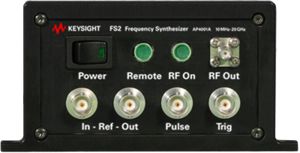
AP4001A FS2 Frequency Synthesizer, 20 GHz


Discover Resources and Insights
Additional Resources for Fast Frequency Switching Test
Related Use Cases


-
![]()
Learn More
How to Generate 5G New Radio Receiver Test Signals
Generate coded 5G new radio (NR) test signals for receiver bit error rate (BER), block error rate (BLER), packet error rate (PER), and frame error rate (FER) validation using PathWave Signal Generation (PWSG) software.
Learn More

-
![]()
Learn More
How to Validate Modulated Load Pull
Validate modulated load pull by measuring amplifier EVM, ACPR, NPR, and nonlinear behavior under wideband RF stimulus.
Learn More
-
![]()
Learn More
How to Validate Ultra Low Noise Voltage
Validate ultra-low noise voltage for oscillators using precision sources.
Learn More

Get in Touch with One of Our Experts
Need help finding the right solution for you?