How to Verify W-Band RF Power in Waveguide Systems

Characterize Performance at the Measurement Plane
Verifying radio frequency (RF) power in W-band systems requires a measurement interface designed for millimeter-wave signals transmitted through waveguide structures. At these frequencies, power may need to be verified at the outputs of sources, frequency extenders, amplifiers, and other waveguide-connected components before they are integrated into a larger system. Loss, mismatch, and connection repeatability within the waveguide path can influence the power available at the measurement plane, making direct measurement at the required interface important when evaluating high-frequency hardware.
The setup connects a W-band waveguide power sensor to a compatible power meter and millimeter-wave source or device under test. Engineers establish the measurement plane, set the frequency, and apply calibration information before measuring average power. Repeating measurements across frequencies or operating conditions verifies available output power and compares component performance. This workflow supports W-band source, component, and subsystem characterization for communications, radar, sensing, and aerospace and defense applications.

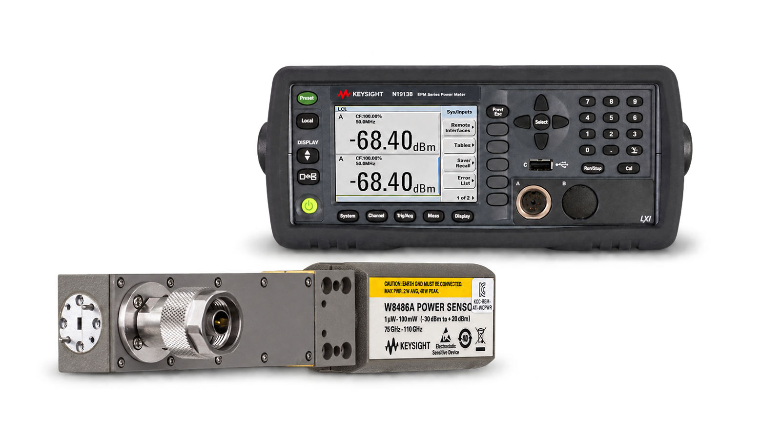
W-Band RF Power Measurement Solution
See Block Diagram of W-Band RF Power Measurement Solution


Explore Products in Our W-Band RF Power Measurement Solution
-

![]()
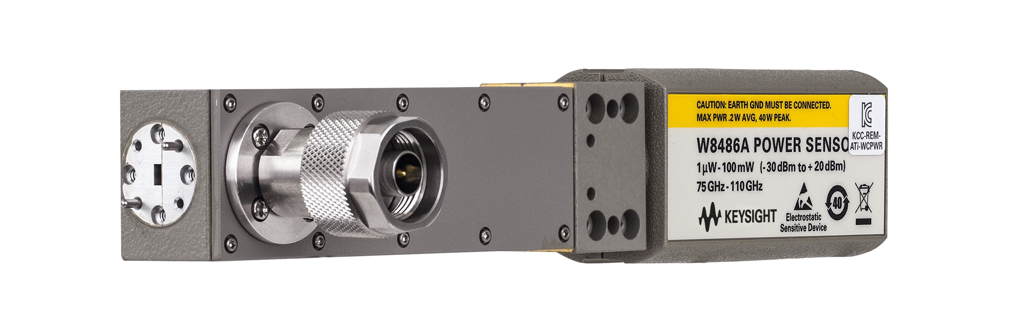
W8486A Waveguide Power Sensor
-
![]()
N1913B EPM Series Single-Channel Power Meter


Discover Resources and Insights
Additional Resources for W-Band RF Power Measurement
Related Use Cases

-
![]()
Learn More
How to Characterize RF Pulse Rise and Fall Time
Characterize radio frequency pulse rise and fall time using a wideband power sensor and power meter for time-domain power measurements.
Learn More

-
![]()
Learn More
How to Analyze Time-Domain Power in Wideband RF Signals
Analyze time-domain power in wideband radio frequency signals using a wideband power sensor and power meter to evaluate dynamic signal behavior.
Learn More
-
![]()
Learn More
How to Capture Fast Power Transitions in Wideband RF Signals
Capture fast power transitions in wideband radio frequency signals using a wideband power sensor and power meter for time-domain analysis.
Learn More

Get in Touch with One of Our Experts
Need help finding the right solution for you?