What are you looking for?
Test Drive Full 3D & Planar 3D EM Simulation Optimized for RF Circuit Designers

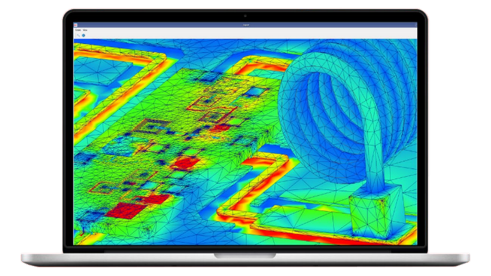
RFPro in ADS Optimizes Full 3D & Planar 3D EM Simulation for RF Circuit Designers
RFPro in Advanced Design System (ADS) integrates FEM and Momentum electromagnetic solvers with circuit simulators for optimal RF circuit design accuracy and efficiency.


Touch or Scan above QR to download RFPro Technical Overview
- RFPro optimizes Full 3D and Planar 3D Electromagnetic (EM) simulation for RF circuit designers to automate EM-circuit cosimulation. Design integrity is always preserved without any layout cutting.
- RFPro ensures circuit simulation accuracy by including EM and impedance effects not accounted for by circuit simulators such as from packaging, 3D interconnects, arbitrary metal shapes, antennas, and geometrical process variations.
- RFPro enables you to select which parts of your design to analyze with EM or with circuit simulation. It automatically combines EM and circuit simulation results in ADS, making it possible to interactively tune and optimize geometrical and electrical parameters together for eliminating unexpected hardware iterations downstream.
Test Drive ADS RFPro


Touch or scan the above QR to get a free trial of ADS RFPro
Upgrade to ADS RFPro with Optimized Full 3D & Planar 3D EM for Circuit Designers


Touch or scan the above QR to get Budgetary Quote for ADS RFPro
Keysight Case Study
Read the figures 1-6 below to see how Keysight instrument R&D team used RFPro in ADS to design the 50 GHz N9042B UXA Signal Analyzer wideband downconverter board.
Accuracy of simulation was confirmed with measurements throughout.

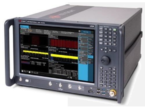
Figure 1. Keysight 50 GHz N9042B UXA Signal Analyzer.

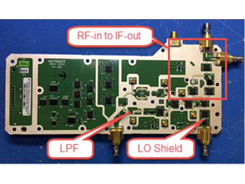
Figure 2. Keysight 50 GHz N9042B UXA Signal Analyzer Downconverter Board.

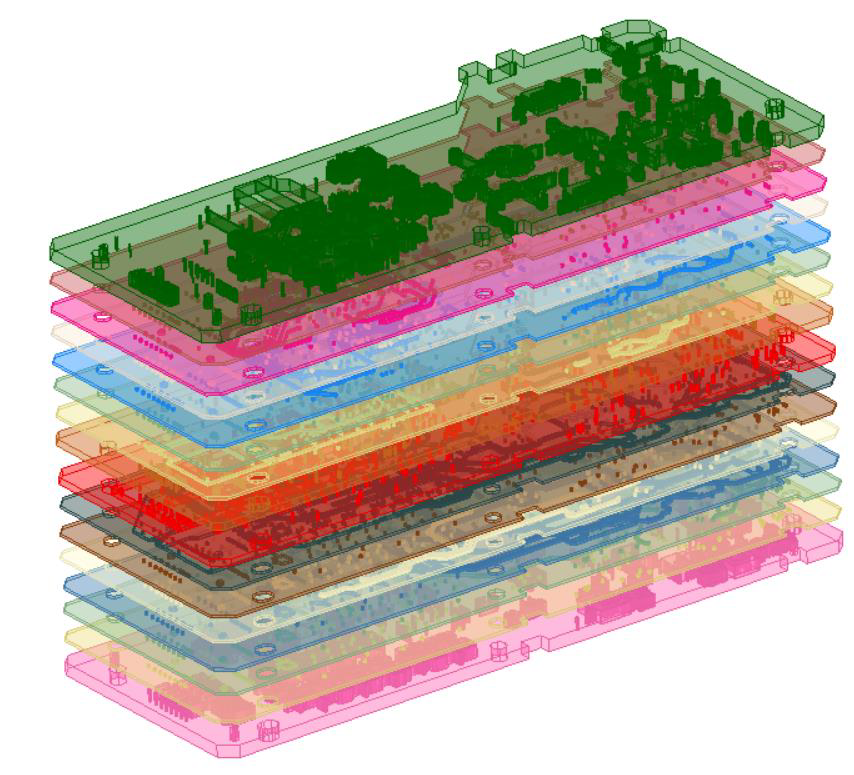
Figure 3. UXA N9042B Signal Analyzer wideband downconverter board. 8" x 4" size, 16 layers, ~250k vias, ~1000 SMT components.

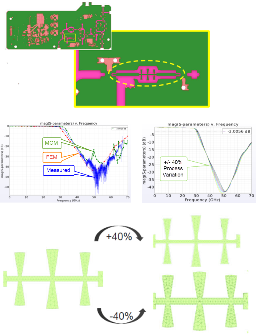
Figure 4. LPF 40% +/- Over/Under etching analysis with fast EM mesh morphing, eliminating need for geometry parameterization, to sign off for production. Accuracy confirmed with measurements.
Figure 5. Shield for LO shows cavity resonance with EMPro Eigenmode Analysis. Fixed with poly-metal absorber. Accuracy confirmed with measurements.

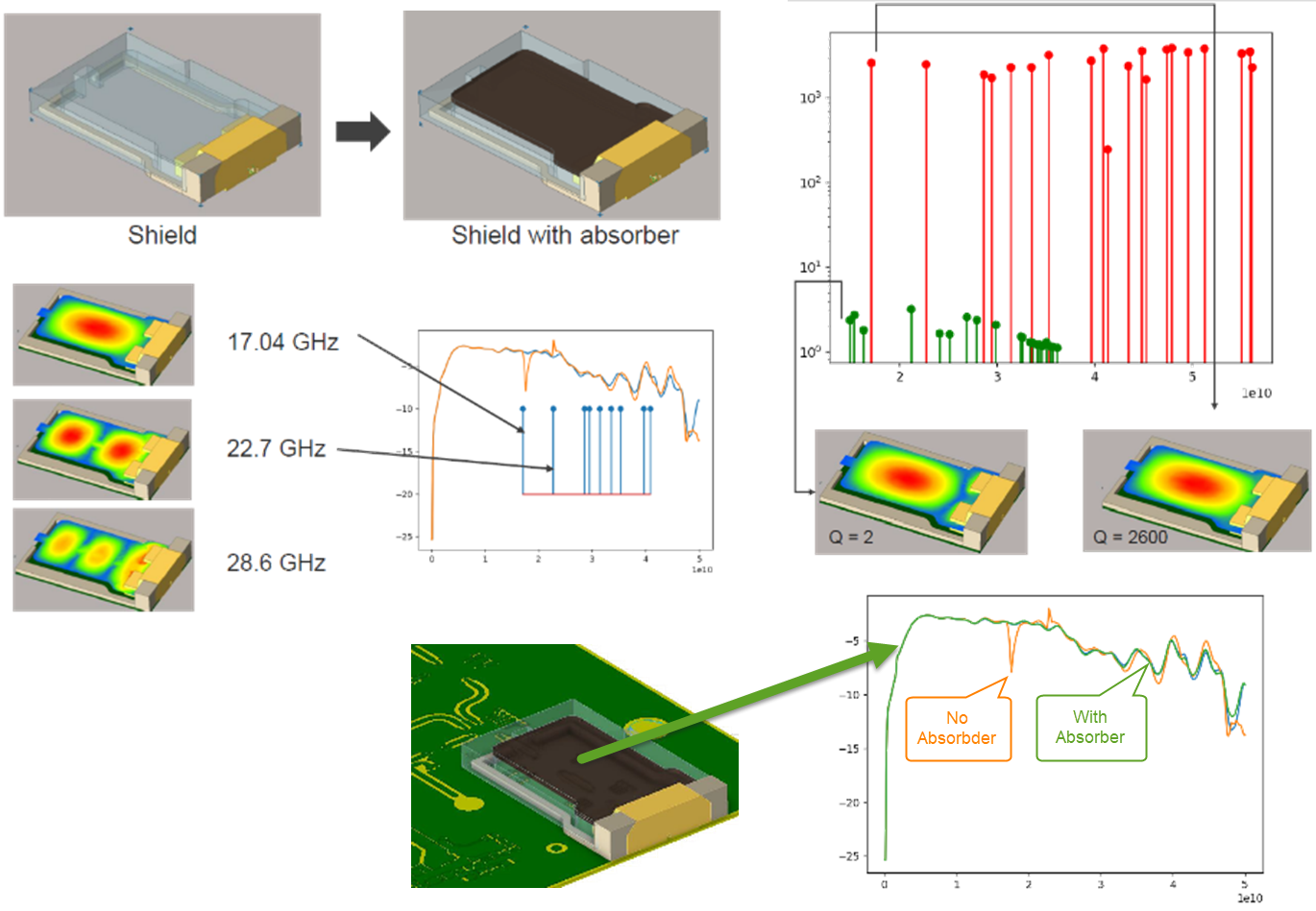

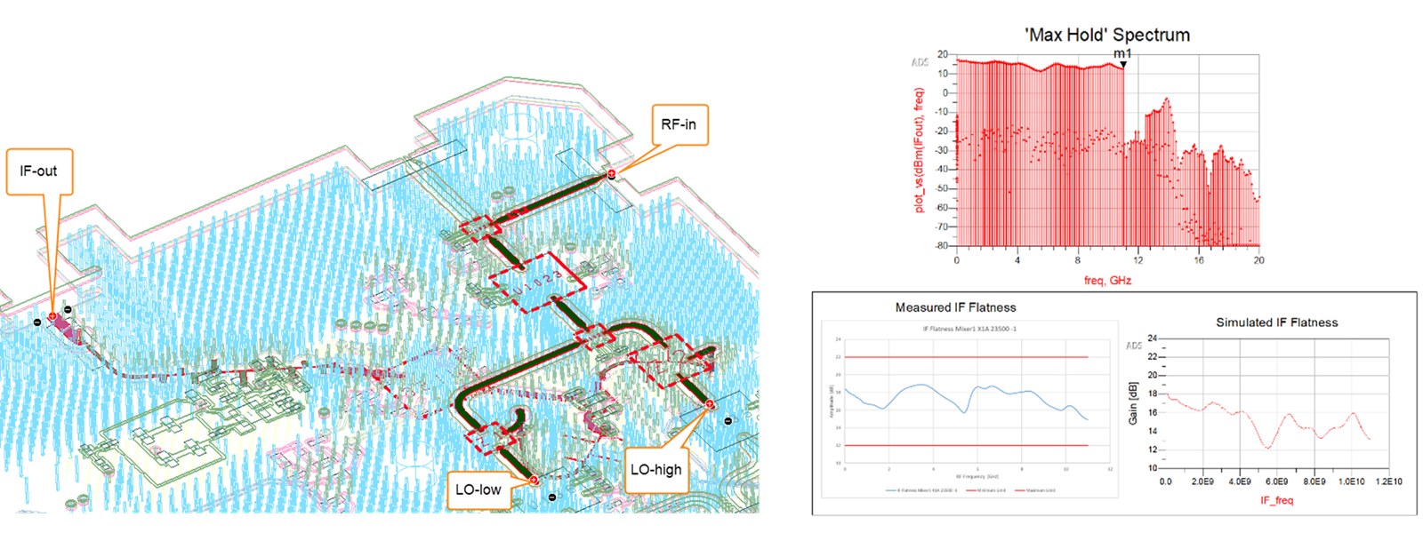
Figure 6. Nonlinear circuit excitation of RF and LO inputs to obtain IF outputs traversing through critical RF paths on the PCB. Analyzed with automatic combination of EM-Circuit results without cutting layout or editing schematic to preserve design integrity and traceability. Accuracy confirmed with measurements.