What are you looking for?
Voltage measurement
1. Basics of voltage measurement
1.1 Various voltmeters and voltage measurements
Voltage measurement is one of the most basic measurements in the electronic measurement. Generally, an electronic measuring instrument is classified roughly by voltage measurement, current (or charge) measurement, and measurement of both (electric power and impedance). For example, the oscilloscope is a measuring instrument that displays the voltage value sensed by the tip of the probe on the screen as a time waveform, and it can be called a voltmeter in a broad sense because the physical value of the target measurement is the voltage. However, at present this is a measuring device focused on the high-speed response and sampling rate exceeding several GHz or more, and generally the precision and resolution of the voltage measurement is not high. The digital multi meter is the most basic ammeter and voltmeter, and various lineups like the hand-held type, bench top type etc. are available. It is most widely used for general voltage measurement because high accuracy and high resolution voltage measurement devices are available, though it does not match the oscilloscope with respect to speed. The electrometer has the function of current and voltage measurement similar to the digital multi meter. When focusing attention on the voltage measurement, it can be positioned with the voltmeter characterized by the high input resistance at the measuring terminal by comparing with the digital multi meter. The advantage of the voltage measurement using the electrometer is described in this document.
1.2 What is the input resistance of a voltmeter?
Figure 1 shows a simplified block diagram when measuring a source voltage (Vdut) using a voltmeter. This is a typical connection when measuring the voltage of the Vdut where the voltmeter is considered as an ideal voltmeter, hence the input resistance of the voltmeter is infinite and the current flowing from the Vdut to the voltmeter is zero amperes. In this ideal case, the voltage reading measured by the voltmeter is the same as the Vdut.
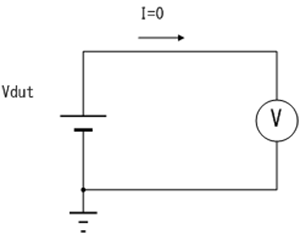
Figure 1 Voltage measurement using an ideal voltmeter
But, in reality, the actual input resistance of any voltmeter is not infinite as the ideal voltmeter, and there exists an input resistance (Rinput) in parallel to the ideal voltmeter as shown in Figure 2. As a result, the current flowing from the voltage source is not zero amperes.
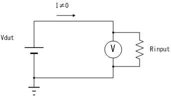
Figure 2 Voltage measurement using a voltmeter with an input resistance
An input resistance of a typical digital multi-meter is 10 MΩ, but there also exists a high-performance digital multi-meter the input resistance of which is more than 10 MΩ. Although an input current, determined by the Vdut/Rinput, is flowing into the voltmeter in these actual measurement conditions, the input current does not affect to the voltage measurement results in the case shown in Figure 2. However, it should be noted that there is a possibility that a finite input resistance causes errors in the voltage measurement results in some cases. The next chapter will look at the cases.
2. Voltage measurement error and its countermeasure
2.1 Voltage measurement error which is caused by the finite input resistance of a voltmeter
In a case where a series resistance between the voltage source and the voltmeter cannot be ignored, the voltage drop generated by this resistance and the input current flowing into the voltmeter is the source of the measurement error.
Figure 3 shows an example where series resistors exist in the connection cables between the voltage source and the voltmeter, where the series resistors include a resistance of the connection cables, a contact resistance of the connector between the cable connections, etc.

Figure 3 The voltage drop by the series resistors in the connection cables
The current I flowing to the series resistance (Rpath) generates a voltage drop (Verr), and this appears as the difference between the voltage source under test and the measurement error of the voltmeter reading. However, the series resistance value such as the one existing between the connection paths is typically from a few mΩ to a few Ω, and this resistance can be considered as negligibly small compared to the input resistance of typically used voltmeters. In this case, since the voltage error is expressed as the ratio of the Rpath and the Rinput (the ratio is in the range of about 10-8 to 10-6), the voltage error caused by the Verror in the connection path can be negligible in most of the applications.
So far, the output resistance of the voltage source is assumed as 0 Ω, but there would be a case that the voltage source under test has an output resistance (Rout) as shown in Figure 4.

Figure 4 The error caused by the output resistance of the voltage source
In the electrical circuit, there are not so many cases where the Rout is large enough to show obvious error in the voltmeter readings, but in such a case where a current source or equivalent is used as the voltage source, the Rout easily exceeds, for example, the value of Rout in the case of performing the voltage measurement using a glass electrode in an electrochemical measurement can reach several 100 MΩ.
The voltage meter reading (Vmeas) is expressed as the ratio of the Vdut, which is the voltage of the voltage source under test, and the sum of the Rout and the Rinput.
It is expressed as;
Vmeas= Vdut ∙ Rinput / (Rout+Rinput)
If the Rout is negligibly small compared to the Rinput, the Vmeas shows almost the same value as the Vdut. However, if the Rout is large enough which cannot be ignored compared to the Rinput, it is a cause of the voltage measurement error. For example, performing a measurement within a 1% error using a voltmeter with a 10 MΩ Rinput resistance, the maximum Rout in the voltage source is limited to 100 kΩ maximum.
As this example shows, for measuring a high output R voltage source, it is important to use a voltmeter with the highest input resistance as possible, since the input resistance of the voltmeter is the cause of the measurement error. As described above, generally the input resistance of the digital multi-meter is in the range of 10 MΩ – 10 GΩ, the input resistance of the electrometer exceeds 100 TΩ.
2.2 The error caused by the insulation resistance of connection cables
Even if the input resistance of the voltmeter is high enough when measuring the voltage from a voltage source with a high output resistance, there is a possibility that the connection cables and the connector itself are the source of error to degrade the measurement accuracy. The input connector of a typical digital multi-meter is a banana plug, and it is common to connect the test leads directly to the banana plug. Or, in a case for shielding the external noise to couple with the measurement signal, a coaxial cable is used with a banana to coaxial converter. In these cases, the voltage of the voltage source is applied between the two test leads or between the center conductor and the shield of the coaxial cable, and the insulation resistance between the test leads or the coaxial cable is seen as the shunt resistance (Rcable) as shown in Figure 5.

(a) The connection using test leads

(b) The connection using a coaxial cable
Figure 5 The insulation resistance of the connection cable appears as a shunt resistance (Rcable)
Figure 5 shows the Rcable as the insulation resistance of the coaxial cable as a simplified circuit, but the Rcable represents all the insulation resistances including the connection connectors regardless of the cable constructions.
The voltmeter reading (Vmeas) is expressed as follows.
Vmeas= Vdut∙(Rinput//Rcable) / (Rout+(Rinput//Rcable))
where, (Rinput//Rcable) represents the parallel connected resistance of the Rinput and the Rcable.
This equation indicates that it is necessary to include the Rcable in addition to the Rinput for considering the measurement accuracy. The insulation resistance of the common coaxial cable is specified as more than 1 GΩ per 1 km in many cases. If converted into the normal length of the cable (around 1 m) used in the measurement, it corresponds to more than 1 TΩ. Although there is a possibility that the insulation resistance value can be higher than the specified value, it can be said that the combination of coaxial cable with a measuring instrument with more than 100 TΩ input resistance such as electrometer is a disproportional combination.
2.3 Method of securing high input resistance using triaxial cable
The triaxial cable connection shown in Figure 6 is effective for eliminating the error by the Rcable component.

Figure 6 The connection using a triaxial cable system
When using the triaxial cable connection, it uses the same connections for both the center conductor and the outer shield as in the case of the coaxial cable. In addition to these two lines, there is an additional inner shield layer which is the same construction as the coaxial cable, between these two metal layers in the triaxial cable, and the voltage of the inner shield is kept as the same voltage as the center conductor. In this case, since the voltage between the center conductor and the inner shield is ideally zero volts even though the insulation resistance Rcable remains the same way, and there is no current flow from the center conductor to the inner shield.
Because there is no current flow from the center conductor to the Rcable, the Rcable does not contribute to the voltage measurement error. This technique to keep the shield line potential the same as the signal line is called the "guard".
The potential difference at both ends of Rcable does not become zero because the offset voltage exists realistically in the guard amplifier that gives potential to an internal shield; and the effect of guard can be expected when the offset voltage is very small compared with the value of Vdut. For example, if the value of Vdut is assumed as 2 V, and if the guard is used because the offset voltage of the usual guard amplifier is about 2 mV, then the insulation resistance Rcable of the cable becomes equivalent to increasing by a factor of 1,000.
Assuming the value of Rcable as 1 TΩ, Vdut of the normal coaxial cable is applied to the Rcable and hence leakage current Ileak that flows to Rcable will be as follows.
Ileak= Vdut/Rcable= 2[V]/1×1012 [Ω]=2×10-12 [A]= 2[pA]
If the guard is given by using the triaxial cable, then the voltage applied to Rcable will not be Vdut but the offset voltage of the guard amplifier Voffset,
Ileak= Voffset/Rcable= 2×10⁻³ [V]/1×1012 [Ω]=2×10-15 [A]=2[fA]
and the leakage current can be suppressed to 1/1000.
2.4 The measurement error caused by the input bias current of a voltmeter
So far, the error caused by the finite value of the input resistance of the voltmeter or the insulation resistance of the measurement cables are shown.
Now, Figure 7 shows another type of error which is caused by the bias current of the voltmeter. The bias current related error is generated even though both the input resistance and the insulation resistance are infinite. The bias current (Ibias) of the voltmeter generates the voltage drop in the output resistance of the voltage source under test, as
Verr = Rout x Ibias.
The bias current is determined by the specification of the voltmeter, and it is important to check this parameter in the selection process of a voltmeter, especially measuring a voltage from a high impedance source.

Figure 7 The effect of the bias current
2.5 Settling time changes by the output resistance of the voltage source
In a case where the output resistance of the voltage source is high, there is an additional error which is dependent by the measurement time. In the voltage measurement for a high resistance voltage source, a coaxial cable is frequently used to connect between the voltmeter and the voltage source for rejecting the influence from the external noise as shown in Figure 8.

Figure 8 The settling time differs by the Rout of the voltage source

Figure 9 The settling of voltage applied to the voltmeter
Since there is a specific capacitance between the signal line and the outer shield in the coaxial cable, a low path filter is created by the output resistance (Rout) of the voltage source and the cable capacitance (Ccable). When the output voltage of the voltage source under test is varied, or a voltmeter is connected to such a voltage source, the test voltage at the voltmeter input changes slowly by the time constant determined by the low path filter.
The time constant (τ) of the low path filter is determined by,
τ = Rout x Ccable.
As an example, in the case Rout = 100 MΩ, Ccable = 1000 pF, the time constant is calculated as,
τ = 100 MΩ x 1000 pF = 100 x 106 x 1000 x 10-12 = 0.1 sec.
Assuming a settling to 0.1% error relative to the final value (at infinite time) of the voltmeter readings, it requires about 7 τ wait time.
0.1 % settling time = 7 x τ = 7 x 0.1 = 0.7 sec.
Therefore, the measurement has to wait for 0.7 seconds, which is the time required to settle into the 0.1 % range after the voltage source is set to a new value. If the measurement is performed without waiting for the settling time, measurement results contained errors.
2.6 Settling improvement by use of guard
As mentioned above, when measuring the measured voltage source of high output resistance, it is necessary to measure by setting the appropriate waiting time in consideration with the settling time, and hence the time required for the measurement becomes long. To avoid this, reduction of the measurement time can be attempted by using the guard similar to 2.3.

Figure 10 Connection using triaxial cable
As shown in Figure 10, the measured voltage source and voltmeter are connected using triaxial cable. The buffer amplifier is fixed at the input of the voltmeter, and the internal shield of triaxial cable is driven. The capacity between the core line of the triaxial cable and internal shield that is the measurement signal line is assumed as Ccable1, and the capacity between the internal shield and external shield is assumed as Ccable2. The voltage acting at both ends of Ccable1 does not become the obstacle of the voltage measurement because it is kept at zero by the buffer amplifier. On the other hand, the same voltage as the voltage value Vdut of the measured voltage source is finally applied at both ends of Ccable2, and it is necessary to charge the Ccable2 in that. The current necessary for this charge does not depend on the value of Rout so that the buffer amplifier sheds the low output resistance and can speed up the settling. It can be said that the use of guard when measuring the measured voltage source with high output resistance value by combining the content of 2.3, that is, the connection using the triaxial cable is necessary.
3. Dealing of external noise
3.1 Penetration of external noise
In a case where both the output resistance of the voltage source under test and the input resistance of the voltmeter are high, it is easily affected by the noise coming from the outside due to the high impedance nature of the connection part between the voltage source and the voltmeter. Figure 11 shows a simplified image the external noise of which is coupling into the measurement circuit.

Figure 11 The noise coming through the capacitive coupling from the external noise source
There are a various noise sources surrounding the outside of the measurement environment. For example, the AC power line cable, the amplitude and frequency of which are roughly 100 V ~ 200 V and 50 or 60 Hz depending on the area in the living, is a source of AC noise. The AC signal is coupled to the measurement cable through the static capacitance (Ccouple), and it affects the measurement results. Figure 12 shows the simplified re-whitening of Figure 11, which shows only the noise components of Figure 11 by removing the DC components.

Figure 12 Simplified equivalent circuit block diagram for noise
Since the impedance of the connection cable portion is expressed as the parallel connection of Rout and Rinput (Rout // Rinput) in the equivalent circuit, the noise which appears at the voltmeter input (Vmeas) is expressed as the impedance division by the Ccouple and the Rout // Rinput of the AC noise source (Vnoise).
Vmeas= Vnoise∙(Rout // Rinput )/(1/(2πf∙Ccouple)+Rout // Rinput)
For reducing the noise from the AC noise source, it is effective to make the Ccouple parameter smaller, and one of such ideas is to apart the noise source away from the voltage measurement circuit block. But this approach is not effective when the Rout // Rinput value is also very high.
The next example shows a case with a realistic number to get a concrete image of AC noise interference.
Here is the assumption number to accurate the example:
- Vnoise: 100 V, 50 Hz
- Ccouple: 0.1 pF
- Rout // Rinput: 100 MΩ
Vmeas=100V∙(100MΩ )/(1/(2π∙50Hz∙0.1pF)+100MΩ)=313mV
The static coupling capacitance of 0.1 pF used in the example is a relatively small number, but it generates about 300 mV noise under the high impedance measurement environments, and just increasing the distance is not always effective. It is effective to use a coaxial type cable to reduce the coupling capacitance, and finally to reduce the noise level.
The shielding by using a coaxial type cabling is always effective, but power line cycle averaging (PLC) is also very effective if the major noise source is only PLC related. If the measurement data is noisy and the PLC averaging is not yet applied, using the PLC averaging would be worth to try as a first choice.
3.2. Shield with coaxial cable
It is effective to use the cable with the coaxial structure to lower the coupling capacity with the noise source. As shown in Figure 13, the current from the noise source will flow at standard potential through the shield, because connecting with the noise source through the electrostatic capacity becomes the potential of the shield, if the coaxial cable is used. Therefore, the inflow of the current for the measurement signal line does not happen, and the effect of the measurement value by the external noise can be suppressed. Here the important thing is to completely enclose the signal wire with the shield potential, and hence it is insufficient to simply change the wiring to the coaxial cable. For example, when the single line wire is changed at the part that connects the end of the coaxial cable to the measured voltage source, it becomes easy for the external noise to penetrate because the measurement signal line is exposed at that part. It is preferable to use the connection method that does not expose the high impedance line as much as possible.

Figure 13 Shielding effectiveness with coaxial cable
3.3. Effect of averaging
The external noise might superimpose the measurement value though it is preferable to suppress the penetration of the external noise with the shield as much as possible. Averaging the measurement value becomes effective at such time. The averaging mentioned here indicates the operation of taking the average of series of measurement values that was repeatedly measured.
It is possible to remove more noise by doing the averaging over a long period of time, because the averaging in principle has the effect similar to the low-pass filter, and it becomes a trade-off with the time required for the measurement.
However, the noise of the commercial power supply frequency is the prime example of the external noise that should be noted in the normal environment as shown in the above-mentioned, and hence it is efficient to set the best averaging time to match with that. If the commercial power source is definitely in the region of 50 Hz, then 1 cycle time will be 20 ms, and hence if the shape of noise waveform is the symmetrical shape of positive and negative like the sine wave, then the noise can be removed by averaging the measurement value at the period of 20 ms.
Such an averaging technique is called PLC (Power Line Cycle) measurement, and most of the electrometers and digital multi meters have the setting function of PLC. The averaging time can be set in the form such as 1 PLC for making the averaging measurement for 1 cycle, 10 PLC for 10 cycles, and it is necessary to note that, if the industrial frequency set to the measuring instrument and the industrial frequency of the actual environment does not match, then the expected effect cannot be sufficiently achieved. The PLC measurement is mentioned in 3.1 of “Low-level current measurement using B2980A series”.
4. Voltage measurement using B2985A/B2987A
4.1 Connection method
This chapter is based on the content to the previous chapter, and describes the connection method and the setting when the voltage measurement with high input resistance is done with B2985A/B2987A. B2985A/B2987A is provided with the triaxial terminal for the voltage measurement at the back panel of the case as shown in the following Figure 14. The value of the input resistance of the voltage measurement terminal reaches 200 TΩ or more.

Figure 14 B2985A/B2987A back panel
This triaxial terminal is connected as shown in Figure 15, and the core conductor is connected with the High side of the voltmeter. The connection of the internal shield can be switched to either the guard potential or the common potential that lies at the low side of the voltmeter, and the external shield is connected with the case.

Figure 15 Connection diagram of voltage measurement terminal of B2985A/B2987A
As per the explanation in the Chapter 2, it is clear that it is advantageous to use the guard in the aspect of voltmeter input resistance and settling, and the best performance of this voltmeter can be demonstrated when the internal shield is set to the guard. However, it is necessary to connect the common potential with separate banana cable, because the common potential will not appear anywhere of the triaxial terminal. Figure 16 shows this connection.

Figure 16 Connection of B2985/B2987A and DUT (When using guard)
In B2985A/B2987A, the common terminal is floating from the potential of the case. This is to enable the voltage measurement of the measured voltage source that is not connected to the earth, and the common voltage allows up to ±500 V for the case. The connection is simple if the common potential can be supplied to the external shield of the triaxial cable, but the user can touch the external shield of the triaxial cable, and hence the user is exposed to danger by the common potential. To avoid this, the common potential is connected with another cable.
When the guard is not used, the connection can be done with one cable by supplying the common potential to the internal shield of the triaxial cable (Figure 17). However, caution is necessary for the occurrence of the insulation resistance effect of the cable and settling effect described in the Chapter 2 in this connection.
The common potential is drawn as completely floating in both the Figure 16 and Figure 17, but such a connection is easily affected by the effect of the external noise. The B2985A/B2987A side can be floating, when the common potential is connected with potential somewhere on the measured voltage source side, but when the measured voltage source side is also floating, then the resistance to the external noise can be improved by connecting the common potential with the case on the B2985A/B2987A side.

Figure 17 Connection of B2985/B2987A and DUT (When guard is not used)
4.2. Setting of averaging
First, the commercial power supply frequency is set when the averaging of measurement value is done with B2985A/B2987A. There are different industrial frequencies of 50 Hz or 60 Hz based on the country and the region, and hence the purpose is to make the averaging time uniform with the industrial frequency to correctly perform the above-mentioned PLC measurement. It is sufficient to only select the Auto Detect of PLC from the menu, because the B2985A/B2987A has the automatic detection function of the industrial frequency. Manual setting is also possible.
The “Coarse Res” button and the “Fine Res” button in the front panel are actually used to change the condition of averaging (Figure 18). If the “Coarse Res” button is pressed, the averaging time becomes short, and if the “Fine Res” button is pressed it conversely becomes long. Usually there are 3 steps of preset for change namely the “Quick”, “Normal”, and “Stable”, and if this “Speed” button that appears at the lower left of the screen during the operation is pressed, the setting by the PLC unit becomes possible (Figure 19).
The setting range is from 0.001 PLC to 100 PLC.

Figure 18 B2985A/B2987A front panel

Figure 19 B2985A/B2987A display screen
Summary
In this document, the precaution and measurement error margin factors in the basic voltage measurement were given, and the countermeasure techniques were explained. The following are the key points.
- In the voltage measurement, the current that flows to the input resistance of the voltmeter becomes the measurement error margin factor of the measurement.
- The insulation resistance of the connecting cable and also the input resistance of the voltmeter itself becomes the measurement error margin factor.
- The insulation resistance of the connecting cable can be shown high in equivalence by using triaxial cable.
- In case the measured voltage source has high output resistance, caution is necessary in the settling based on the capacity of the cable.
- The settling time can be improved by using guard.
- Voltage measurement of high input resistance is easily affected by the penetration of the external noise.
- The shield is effective for the external noise.
- Effect of averaging on noise of commercial power supply frequency.
The setup when actually doing the voltage measurement by using B2985A/B2987A based on these was explained.