Learn More
segmentation:business-unit/CSG,segmentation:campaign/Cellular,segmentation:product-category/Cellular_Device_Network_Testing,segmentation:product-category/Cellular_Device_Network_Testing/Cellular_Device_Testing,keysight:product-lines/13,segmentation:funnel/bofu,keysight:dtx/solutions/facets/development-area/rf,keysight:dtx/solutions/facets/design-and-test-product/wireless-emulator,keysight:dtx/solutions/facets/workflow-stage/manufacturing,keysight:dtx/solutions/facets/industry/wireless-communications,keysight:models/f9/f9681asegmentation:business-unit/CSG,segmentation:campaign/Cellular,segmentation:product-category/Cellular_Device_Network_Testing,segmentation:product-category/Cellular_Device_Network_Testing/Cellular_Device_Testing,keysight:product-lines/13,segmentation:funnel/bofu,keysight:dtx/solutions/facets/development-area/rf,keysight:dtx/solutions/facets/design-and-test-product/wireless-emulator,keysight:dtx/solutions/facets/workflow-stage/manufacturing,keysight:dtx/solutions/facets/industry/wireless-communications,keysight:models/f9/f9681asegmentation:business-unit/CSG,segmentation:campaign/Cellular,segmentation:product-category/Cellular_Device_Network_Testing,segmentation:product-category/Cellular_Device_Network_Testing/Cellular_Device_Testing,keysight:product-lines/13,segmentation:funnel/bofu,keysight:dtx/solutions/facets/development-area/rf,keysight:dtx/solutions/facets/design-and-test-product/wireless-emulator,keysight:dtx/solutions/facets/workflow-stage/manufacturing,keysight:dtx/solutions/facets/industry/wireless-communications,keysight:models/f9/f9681asegmentation:business-unit/CSG,segmentation:campaign/Cellular,segmentation:product-category/Cellular_Device_Network_Testing,segmentation:product-category/Cellular_Device_Network_Testing/Cellular_Device_Testing,keysight:product-lines/13,segmentation:funnel/bofu,keysight:dtx/solutions/facets/development-area/rf,keysight:dtx/solutions/facets/design-and-test-product/wireless-emulator,keysight:dtx/solutions/facets/workflow-stage/manufacturing,keysight:dtx/solutions/facets/industry/wireless-communications,keysight:models/f9/f9681asegmentation:business-unit/CSG,segmentation:campaign/Cellular,segmentation:product-category/Cellular_Device_Network_Testing,segmentation:product-category/Cellular_Device_Network_Testing/Cellular_Device_Testing,keysight:product-lines/13,segmentation:funnel/bofu,keysight:dtx/solutions/facets/development-area/rf,keysight:dtx/solutions/facets/design-and-test-product/wireless-emulator,keysight:dtx/solutions/facets/workflow-stage/manufacturing,keysight:dtx/solutions/facets/industry/wireless-communications,keysight:models/f9/f9681asegmentation:business-unit/CSG,segmentation:campaign/Cellular,segmentation:product-category/Cellular_Device_Network_Testing,segmentation:product-category/Cellular_Device_Network_Testing/Cellular_Device_Testing,keysight:product-lines/13,segmentation:funnel/bofu,keysight:dtx/solutions/facets/development-area/rf,keysight:dtx/solutions/facets/design-and-test-product/wireless-emulator,keysight:dtx/solutions/facets/workflow-stage/manufacturing,keysight:dtx/solutions/facets/industry/wireless-communications,keysight:models/f9/f9681asegmentation:business-unit/CSG,segmentation:campaign/Cellular,segmentation:product-category/Cellular_Device_Network_Testing,segmentation:product-category/Cellular_Device_Network_Testing/Cellular_Device_Testing,keysight:product-lines/13,segmentation:funnel/bofu,keysight:dtx/solutions/facets/development-area/rf,keysight:dtx/solutions/facets/design-and-test-product/wireless-emulator,keysight:dtx/solutions/facets/workflow-stage/manufacturing,keysight:dtx/solutions/facets/industry/wireless-communications,keysight:models/f9/f9681asegmentation:business-unit/CSG,segmentation:campaign/Cellular,segmentation:product-category/Cellular_Device_Network_Testing,segmentation:product-category/Cellular_Device_Network_Testing/Cellular_Device_Testing,keysight:product-lines/13,segmentation:funnel/bofu,keysight:dtx/solutions/facets/development-area/rf,keysight:dtx/solutions/facets/design-and-test-product/wireless-emulator,keysight:dtx/solutions/facets/workflow-stage/manufacturing,keysight:dtx/solutions/facets/industry/wireless-communications,keysight:models/f9/f9681asegmentation:business-unit/CSG,segmentation:campaign/Cellular,segmentation:product-category/Cellular_Device_Network_Testing,segmentation:product-category/Cellular_Device_Network_Testing/Cellular_Device_Testing,keysight:product-lines/13,segmentation:funnel/bofu,keysight:dtx/solutions/facets/development-area/rf,keysight:dtx/solutions/facets/design-and-test-product/wireless-emulator,keysight:dtx/solutions/facets/workflow-stage/manufacturing,keysight:dtx/solutions/facets/industry/wireless-communications,keysight:models/f9/f9681asegmentation:business-unit/CSG,segmentation:campaign/Cellular,segmentation:product-category/Cellular_Device_Network_Testing,segmentation:product-category/Cellular_Device_Network_Testing/Cellular_Device_Testing,keysight:product-lines/13,segmentation:funnel/bofu,keysight:dtx/solutions/facets/development-area/rf,keysight:dtx/solutions/facets/design-and-test-product/wireless-emulator,keysight:dtx/solutions/facets/workflow-stage/manufacturing,keysight:dtx/solutions/facets/industry/wireless-communications,keysight:models/f9/f9681asegmentation:business-unit/CSG,segmentation:campaign/Cellular,segmentation:product-category/Cellular_Device_Network_Testing,segmentation:product-category/Cellular_Device_Network_Testing/Cellular_Device_Testing,keysight:product-lines/13,segmentation:funnel/bofu,keysight:dtx/solutions/facets/development-area/rf,keysight:dtx/solutions/facets/design-and-test-product/wireless-emulator,keysight:dtx/solutions/facets/workflow-stage/manufacturing,keysight:dtx/solutions/facets/industry/wireless-communications,keysight:models/f9/f9681a
How to Verify 5G FR2 Devices OTA
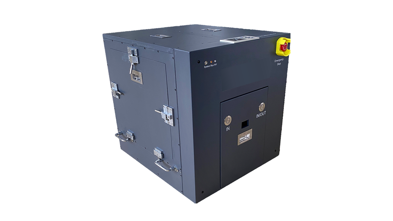
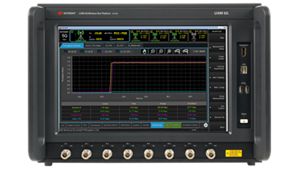
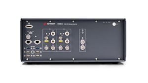
Verify 5G FR2 devices over the air using a compact chamber, adjustable antennas, integrated switching, and mmWave radio-head connectivity.
Learn More