How to Characterize Amplifier Intermodulation Distortion and IP3

IP3 Characterization Solution
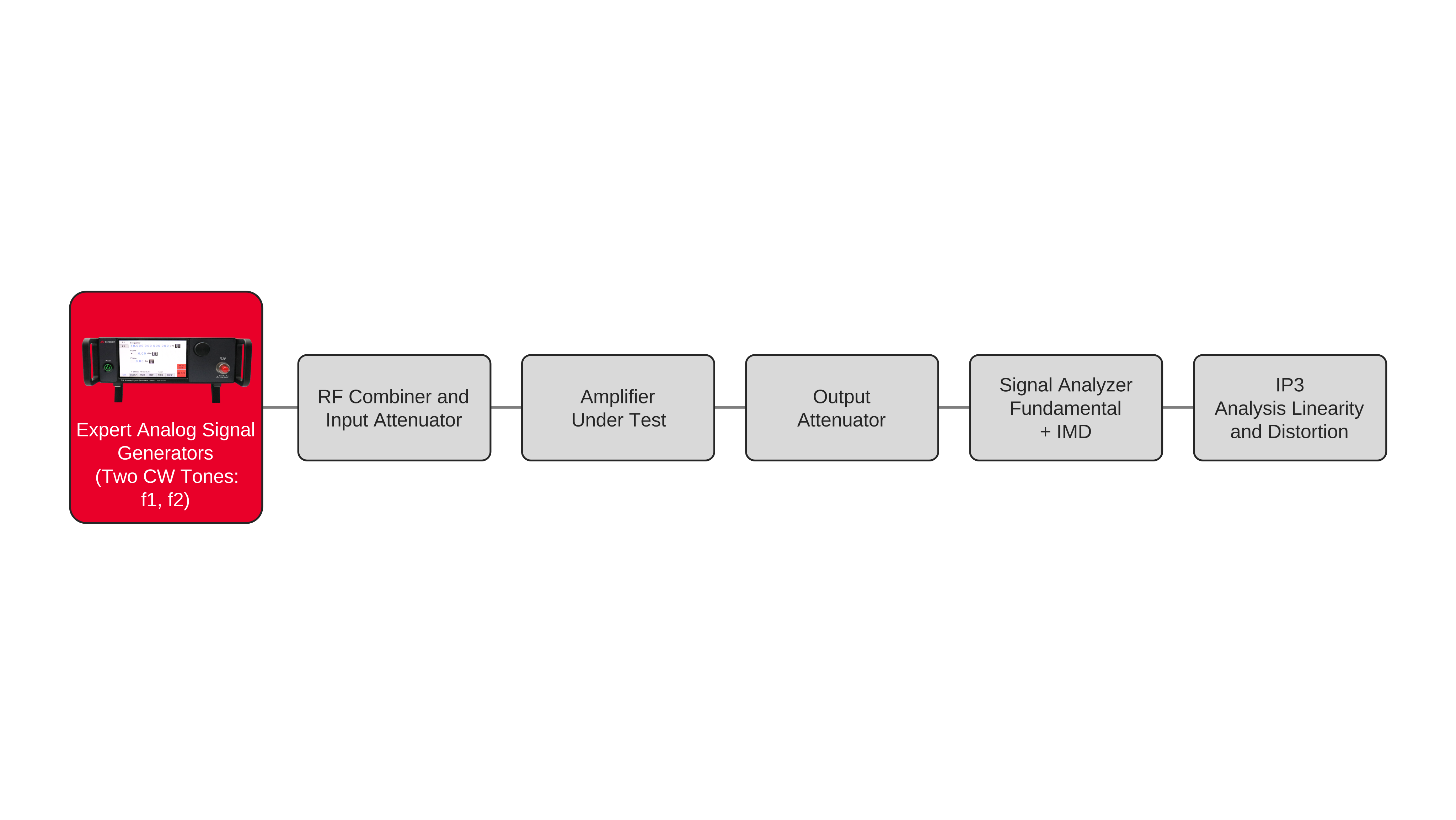
Characterizing amplifier intermodulation distortion and third-order intercept point (IP3) requires two continuous-wave RF signals with closely spaced frequencies, controlled output levels, and sufficient spectral purity to avoid introducing unwanted distortion into the measurement. The two signals are combined and applied simultaneously to the amplifier input, producing the desired fundamental output tones along with intermodulation products generated by amplifier nonlinearities. A signal analyzer measures the fundamental tones and third-order intermodulation products, typically located at frequencies 2f1 − f2 and 2f2 − f1. The test setup requires careful control of source power, tone spacing, combining losses, and analyzer settings so the measured intermodulation distortion represents the amplifier response rather than distortion generated by the test equipment.
To determine IP3, engineers repeat the two-tone measurement while varying the amplifier input power and recording the resulting fundamental and third-order intermodulation levels. The fundamental output tones increase approximately linearly with input power in the amplifier's linear operating region, while third-order intermodulation products increase at a higher rate. These measured levels can be used to extrapolate the fundamental and third-order responses to their theoretical intersection, establishing the third-order intercept point. Input-referred IP3 or output-referred IP3 can then be calculated according to the measurement reference plane. Repeating the measurement across frequency, tone spacing, or amplifier operating conditions provides intermodulation distortion and IP3 characterization across the required RF operating range.

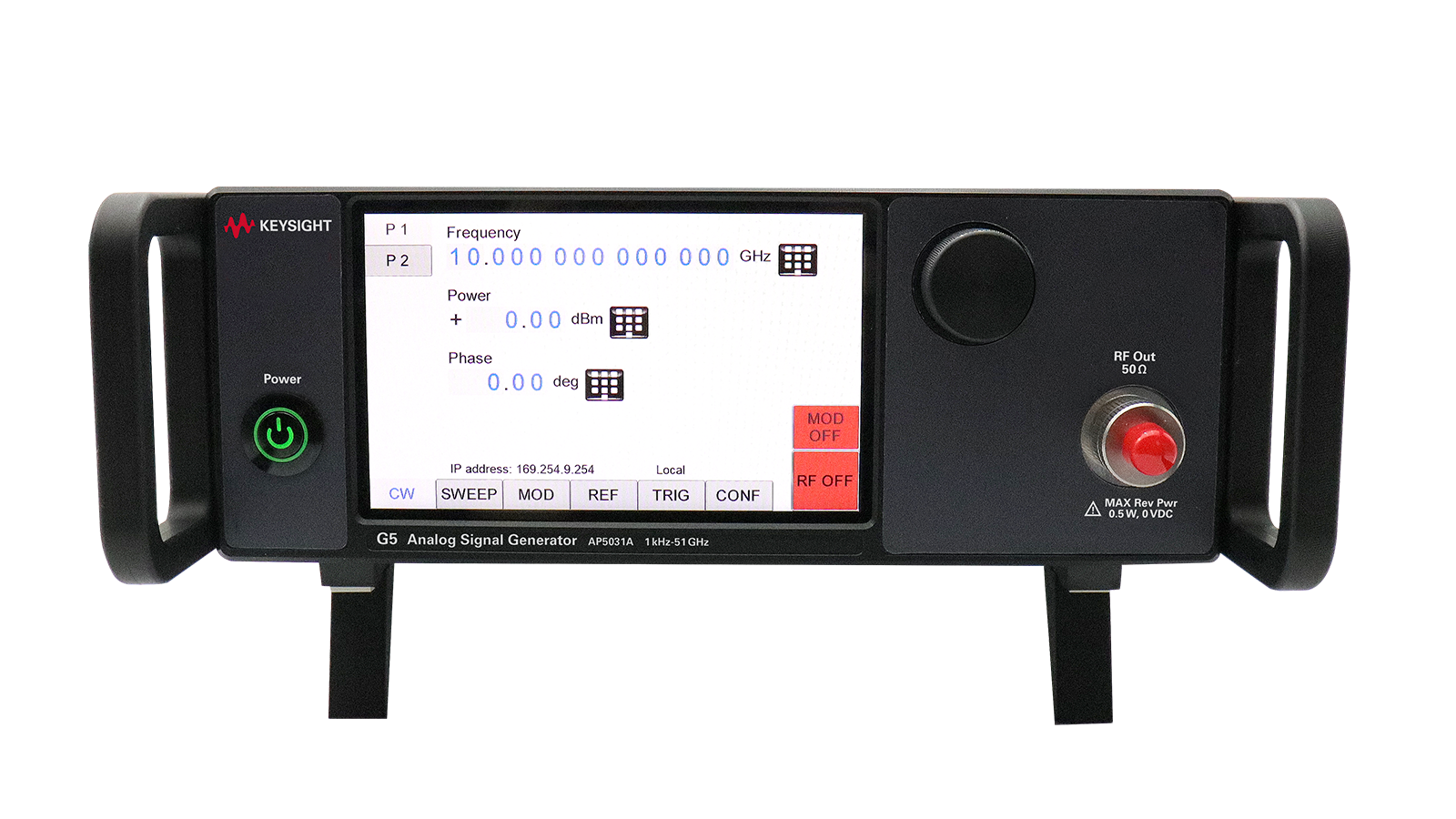
IP3 Characterization Solution
See Block Diagram of IP3 Characterization Solution

Explore Products in Our IP3 Characterization Solution
-


![]()
AP5032A Analog Signal Generator, 1 kHz to 51 GHz
-
![]()
AP5031A Analog Signal Generator, 1 kHz to 90 GHz


Discover Resources and Insights
Additional Resources for Characterizing Amplifier Intermodulation Distortion and IP3
Related Use Cases

-
![]()
Learn More
How to Perform IoT RF Receiver Testing
Validate IoT receiver sensitivity and robustness with controlled RF signals from the N5166B.
Learn More

-
![]()
Learn More
How to Create Custom I/Q Waveforms
Create and download custom baseband I/Q waveforms with the N5166B for flexible RF signal generation and receiver test.
Learn More
-
![]()
Learn More
How to Generate Interference Signals for Receiver Testing
Use the Keysight N5166B Essential Vector Signal Generator to generate controlled RF interference signals for receiver robustness and coexistence testing.
Learn More

Get in Touch with One of Our Experts
Need help finding the right solution for you?