


Title
Triggered pulse, level stepped down (settable to \-130 dBm, accuracy specified to \-90 dBm)
Tech Guide
Radar Target Simulation Guide: Range, Doppler, and EW Threat Scenarios on the E8267D

Radar target simulation can start with a quote for a dedicated simulator when the bench has to be ready before the receiver hardware arrives. What is not always clear at that point is which planned tests a signal generator could run instead. This guide maps range, Doppler, and radar cross section to signal generator settings, shows where a closed-loop simulator is still required, and uses the E8267D PSG vector signal generator as the worked example.
Every E8267D figure below comes from Keysight data sheet 5989-0697EN, the E8267D configuration guide 5989-1326EN, or a named Keysight help page or application note.
Summary
- Radar target simulation gives the receiver a return with a set range, velocity, and size: a delay, a Doppler offset, and an output level.
- A triggered signal generator covers open-loop receiver tests. Tests that must return the radar's own pulse need a closed loop.
- Round-trip delay is 6.67 µs per km, so 10 ns moves a target about 1.5 m, and 300 m/s at 10 GHz shifts about 20 kHz.
- The E8267D PSG vector signal generator tunes 100 kHz to 44 GHz (specified from 250 kHz) with Option 544, plays waveforms up to 80 MHz wide with Option 602, and reaches 20 ns pulses above 400 MHz (ALC off) with Option UNW.
- Certified used equipment from Keysight can save 40 to 90% compared with list price (Keysight Used), with up to 5 years of warranty options. See the certified used E8267D and request a quote.
What Is Radar Target Simulation?
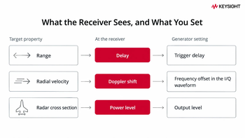
Radar target simulation produces a signal at a radar receiver that looks like an echo from a target, with a range, a radial velocity, and a radar cross section (RCS). To the receiver, that target is three numbers: a delay, a frequency offset, and a power level. Range maps to time because the echo arrives after the round trip. Velocity maps to frequency because a closing target raises the return frequency through Doppler shift. Size maps to amplitude because a larger RCS reflects more power.
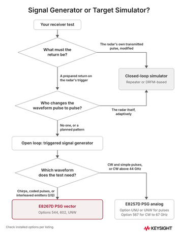
An open-loop setup plays a prepared return each time the radar's timing triggers it. A closed-loop setup captures the radar's own transmitted pulse, modifies it, and sends it back. For more on the instrument itself, see what a signal generator does, RF signal generator basics, or the signal generator buying guide.
Many product pages on this topic focus on 77 GHz automotive simulators. This guide covers microwave radar and electronic warfare (EW) receivers from L to Ka band. Automotive radar at 76 to 81 GHz has dedicated simulators such as Keysight's E8718A.
Do You Need a Target Simulator or a Signal Generator?
If a test only needs a timed, shaped return at the receiver, a triggered signal generator can run it. If it needs the radar's own transmitted pulse returned, it needs a closed-loop simulator. A signal generator can typically run:
- Receiver sensitivity and minimum detectable signal.
- Pulse compression and range sidelobes.
- Pulse repetition interval (PRI) tracking and pulse descriptor word (PDW) output.
- Constant false alarm rate (CFAR) behavior against a modeled background.
- Emitter identification in an EW receiver.
End-to-end coherence checks, pulse-to-pulse waveform changes made by the radar itself, and full-system tests typically need a closed-loop repeater or digital RF memory (DRFM)-based simulator.
Keysight Application Note 5992-0094EN makes the schedule case: lab testing runs early in a program and repeats easily, while flight testing comes later and costs more. For instruments beyond the source, see Keysight test equipment for aerospace and defense.
| Test | Signal generator route | Closed loop needed? |
|---|---|---|
| Sensitivity | Triggered pulse, level stepped down (settable to \-130 dBm, accuracy specified to \-90 dBm) | No |
| Pulse compression | Linear FM (LFM) or coded pulse built in N7620B | No |
| PRI tracking and PDW output | Sequenced segments | No |
| CFAR against a background | Option 403 noise with a waveform model | No (fidelity depends on the model) |
| End-to-end coherence | Typically needs a closed loop | Yes |
Test
Signal generator route
Closed loop needed?
Sensitivity
Title
No
No
Pulse compression
Title
Linear FM (LFM) or coded pulse built in <a href="https://www.keysight.com/us/en/product/N7620B/pathwave-signal-generation-pulse-building.html">N7620B</a>
Linear FM (LFM) or coded pulse built in <a href="https://www.keysight.com/us/en/product/N7620B/pathwave-signal-generation-pulse-building.html">N7620B</a>
Title
No
No
PRI tracking and PDW output
Title
Sequenced segments
Sequenced segments
Title
No
No
CFAR against a background
Title
Option 403 noise with a waveform model
Option 403 noise with a waveform model
Title
No (fidelity depends on the model)
No (fidelity depends on the model)
End-to-end coherence
Title
Typically needs a closed loop
Typically needs a closed loop
Title
Yes
Yes
Know which tests your bench must run? Browse the certified used inventory and request a quote with your test list.
How Do Range, Doppler, and RCS Map to Signal Generator Settings?
Range maps to trigger delay, Doppler to a frequency offset in the in-phase and quadrature (I/Q) waveform, and RCS to output level. Delay and frequency offset are calculated directly from range and velocity. Output level is where the source specification can decide how far the test can go.
| Target property | Physics | Generator setting | Worked number | E8267D limit (with option) |
|---|---|---|---|---|
| Range | Two-way delay, 2R/c | Trigger delay | 1 km \= 6.67 µs; 10 ns \= about 1.5 m | 10 ns to 40 s in 10 ns steps (Option 602\) |
| Radial velocity | Doppler, fd \= 2vf/c | Frequency offset in the I/Q waveform | 300 m/s at 10 GHz \= about 20 kHz | Within 80 MHz (Option 602\) |
| Radar cross section | Return scales as RCS/R⁴ | Output level | Doubling range \= about \-12 dB | Settable to \-130 dBm (accuracy specified to \-90 dBm; standard) |
Target property
Physics
Generator setting
Worked number
E8267D limit (with option)
Range
Title
Two-way delay, 2R/c
Two-way delay, 2R/c
Title
Trigger delay
Trigger delay
Title
1 km \= 6.67 µs; 10 ns \= about 1.5 m
1 km \= 6.67 µs; 10 ns \= about 1.5 m
Title
10 ns to 40 s in 10 ns steps (Option 602\)
10 ns to 40 s in 10 ns steps (Option 602\)
Radial velocity
Title
Doppler, fd \= 2vf/c
Doppler, fd \= 2vf/c
Title
Frequency offset in the I/Q waveform
Frequency offset in the I/Q waveform
Title
300 m/s at 10 GHz \= about 20 kHz
300 m/s at 10 GHz \= about 20 kHz
Title
Within 80 MHz (Option 602\)
Within 80 MHz (Option 602\)
Radar cross section
Title
Return scales as RCS/R⁴
Return scales as RCS/R⁴
Title
Output level
Output level
Title
Doubling range \= about \-12 dB
Doubling range \= about \-12 dB
Title
Settable to \-130 dBm (accuracy specified to \-90 dBm; standard)
Settable to \-130 dBm (accuracy specified to \-90 dBm; standard)
How Does Trigger Delay Set the Simulated Range?
Every 10 ns of delay moves the simulated target about 1.5 m. Keysight Application Note 5992-0544EN uses the same relationship for maximum unambiguous range: the speed of light multiplied by the pulse repetition interval, divided by 2. A target 1 km away returns after 6.67 µs.
With Option 602, the E8267D supports an external trigger delay of 10 ns to 40 s in 10 ns steps.
For simple pulsed returns, the internal pulse generator (Option UNU or UNW) sets a triggered delay of 75 ns to 42 s, with plus or minus 10 ns of jitter, or about plus or minus 1.5 m. The 75 ns minimum adds about 11 m, which can matter for very short ranges.
How Do You Write Doppler into the I/Q Waveform?
Doppler is a kilohertz-scale offset, well inside an 80 MHz baseband. The radar model in Keysight Application Note 5992-0544EN derives velocity from the Doppler shift and the carrier frequency, which rearranges to fd = 2vf/c. A 300 m/s target on a 10 GHz radar shifts about 20 kHz, and a 1,000 m/s target at 44 GHz shifts about 294 kHz.
On the E8267D, write the offset into the Option 602 waveform as a baseband frequency shift, so the carrier stays at the radar's center frequency, to within the timebase accuracy. Lock the generator and the radar to a common 10 MHz reference so the offset is only the Doppler shift. Pulse-Doppler radars read the shift as phase change across pulses, so build the pulse train in N7620B, where each pulse's phase can be set.
How Does Output Level Stand In for Radar Cross Section?
The level setting follows the rule in Keysight Application Note 5989-7575EN, Radar Measurements: received power is proportional to RCS and inversely proportional to range⁴. The return falls about 12 dB each time range doubles, so level range and accuracy can decide what the test reaches.
Set the generator to the return level the link budget predicts at the receiver input. Then treat RCS changes as dB offsets: twice the RCS returns about 3 dB more. This treats RCS as constant. A fluctuating target needs the level to vary from scan to scan or pulse to pulse in the waveform. The E8267D sets levels down to -130 dBm with a 0 to 115 dB step attenuator in 5 dB steps. Data sheet 5989-0697EN lists CW level accuracy of plus or minus 0.8 dB at 2 to 20 GHz between +10 and -10 dBm (15 to 35 °C) and specifies level accuracy only down to -90 dBm (plus or minus 1.0 dB at 2 to 20 GHz).
What Can the E8267D PSG Vector Signal Generator Simulate?
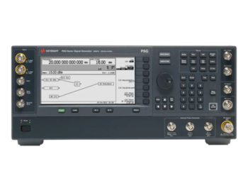
The E8267D PSG Vector Signal Generator is the vector model in Keysight's PSG family, a single-output microwave source. It covers 100 kHz to 44 GHz with an 80 MHz internal baseband when Options 544 and 602 are installed. The table values come from data sheet 5989-0697EN (and the configuration guide or Signal Studio help where noted). The E8267D product page lists the options. Pulse widths apply with automatic level control (ALC) off, after a power search.
| Specification | Value | Option | Radar use |
|---|---|---|---|
| Frequency range | 100 kHz to 44 GHz tunable (specified from 250 kHz) | 544 | L through Ka band |
| Continuous wave (CW) output power (spec) | \+20 dBm at 0.4 to 3.2 GHz (Option 1EH filters off); \+14 dBm at 3.2 to 32 GHz; \+12 dBm at 32 to 40 GHz; \+10 dBm at 40 to 44 GHz | 544 | Headroom for losses |
| Minimum settable level | \-130 dBm (level accuracy specified to \-90 dBm) | Standard | Small, distant returns |
| Internal baseband | Up to 80 MHz; 2 channels, 16-bit; 64 MSa per channel (8 MSa on units with the older Option 601, per Signal Studio help); 8,192 segments; 16,384 sequences | 602 | Chirps, Doppler, emitters |
| Minimum pulse width | 20 ns (ALC off, above 400 MHz) | UNW | Narrow pulses |
| Pulse on/off ratio | 80 dB (specified; typical with UNU) | UNW | Clean pulse floor |
| Wideband external I/Q | DC to 1.0 GHz baseband above 3.2 GHz (up to 2 GHz of RF modulation bandwidth, per the configuration guide) | 016 | Waveforms over 80 MHz |
| Calibrated noise | 50 kHz to 15 MHz bandwidth added to an arbitrary waveform; 50 kHz to 80 MHz in real-time mode | 403 | Known signal-to-noise ratio |
Specification
Value
Option
Radar use
Frequency range
Title
100 kHz to 44 GHz tunable (specified from 250 kHz)
100 kHz to 44 GHz tunable (specified from 250 kHz)
Title
544
544
Title
L through Ka band
L through Ka band
Continuous wave (CW) output power (spec)
Title
\+20 dBm at 0.4 to 3.2 GHz (Option 1EH filters off); \+14 dBm at 3.2 to 32 GHz; \+12 dBm at 32 to 40 GHz; \+10 dBm at 40 to 44 GHz
\+20 dBm at 0.4 to 3.2 GHz (Option 1EH filters off); \+14 dBm at 3.2 to 32 GHz; \+12 dBm at 32 to 40 GHz; \+10 dBm at 40 to 44 GHz
Title
544
544
Title
Headroom for losses
Headroom for losses
Minimum settable level
Title
\-130 dBm (level accuracy specified to \-90 dBm)
\-130 dBm (level accuracy specified to \-90 dBm)
Title
Standard
Standard
Title
Small, distant returns
Small, distant returns
Internal baseband
Title
Up to 80 MHz; 2 channels, 16-bit; 64 MSa per channel (8 MSa on units with the older Option 601, per Signal Studio help); 8,192 segments; 16,384 sequences
Up to 80 MHz; 2 channels, 16-bit; 64 MSa per channel (8 MSa on units with the older Option 601, per Signal Studio help); 8,192 segments; 16,384 sequences
Title
602
602
Title
Chirps, Doppler, emitters
Chirps, Doppler, emitters
Minimum pulse width
Title
20 ns (ALC off, above 400 MHz)
20 ns (ALC off, above 400 MHz)
Title
UNW
UNW
Title
Narrow pulses
Narrow pulses
Pulse on/off ratio
Title
80 dB (specified; typical with UNU)
80 dB (specified; typical with UNU)
Title
UNW
UNW
Title
Clean pulse floor
Clean pulse floor
Wideband external I/Q
Title
DC to 1.0 GHz baseband above 3.2 GHz (up to 2 GHz of RF modulation bandwidth, per the configuration guide)
DC to 1.0 GHz baseband above 3.2 GHz (up to 2 GHz of RF modulation bandwidth, per the configuration guide)
Title
016
016
Title
Waveforms over 80 MHz
Waveforms over 80 MHz
Calibrated noise
Title
50 kHz to 15 MHz bandwidth added to an arbitrary waveform; 50 kHz to 80 MHz in real-time mode
50 kHz to 15 MHz bandwidth added to an arbitrary waveform; 50 kHz to 80 MHz in real-time mode
Title
403
403
Title
Known signal-to-noise ratio
Known signal-to-noise ratio
Pulse patterns, chirps, and coded pulses are built in N7620B PathWave Signal Generation for pulse building. At 1 GHz, phase noise is specified at -130 dBc/Hz at a 20 kHz offset as standard (-134 dBc/Hz typical), and -138 dBc/Hz at a 10 kHz offset with Option UNY (-143 dBc/Hz typical), with the specifications applying from 15 to 35 °C. The Option UNY values apply in the mode optimized for offsets below 150 kHz. The two are given at different offsets, so they are not a like-for-like comparison. Phase noise rises with carrier frequency: at a 20 kHz offset the standard unit is specified at -110 dBc/Hz from 3.2 to 10 GHz (-113 dBc/Hz typical) and -104 dBc/Hz from 10 to 20 GHz (-108 dBc/Hz typical).
Because Keysight designs and builds the E8267D, the Official Keysight Used Equipment Store can help you match a certified used E8267D PSG vector signal generator to your test plan. A certified used unit's installed options are confirmed on its listing.
Which Pulse Specifications Decide a Radar Receiver Test?
Option UNW brings the minimum pulse width down to 20 ns (ALC off, above 400 MHz), against 150 ns with Option UNU. The data sheet's other pulse figures:
- Rise and fall time above 400 MHz: 10 ns specified, 6 ns typical (UNW).
- Repetition frequency with ALC off: DC to 10 MHz (UNW).
- Pulse period (PRI): 70 ns to 42 s, 10 ns resolution (internal pulse generator, UNU or UNW; 70 ns is 14.28 MHz, above UNW's 10 MHz ALC-off repetition specification, so check the combination).
- Modes: free-run, triggered, triggered with delay, doublet, and gated; the last three need an external trigger.
Option HNS gives UNW performance below 31.8 GHz and UNU performance above it, so check the pulse option on each listing.
When narrow pulses are part of the plan, this option can decide time-of-arrival tests. A 150 ns minimum cannot represent a 50 ns pulse, and a slower leading edge can widen the arrival-time uncertainty. Keysight's data sheet shows a measured pulse envelope at 9 GHz and 10 dBm with ALC off, using 10 ns per division (measured data, not a specification).
How Much Modulation Bandwidth Does Your Waveform Need?
If the radar chirp needs more than 80 MHz of frequency sweep, the answer is a second input path. Range resolution is c divided by twice the bandwidth: about 1.9 m at 80 MHz and about 7.5 cm at 2 GHz. A 2011 Georgia Tech Research Institute tutorial published by NTIA tabulates the same series for LFM: 100 MHz gives 1.5 m, and 10 MHz gives 15 m.
Waveforms up to 80 MHz fit the internal baseband path with Option 602. The configuration guide lists 160 MHz of RF modulation bandwidth for the standard external I/Q inputs (typical flatness plus or minus 1 dB within plus or minus 40 MHz of the carrier, per the data sheet). Wider waveforms use the Option 016 wideband external I/Q inputs, which provide DC to 1.0 GHz of baseband above 3.2 GHz when fed by an external Keysight arbitrary waveform generator (AWG). The configuration guide and Keysight's Signal Studio help (I/Q path, E8267D PSG only) both give that path up to 2 GHz of RF modulation bandwidth, the guide above 3.2 GHz. Keysight Application Note 5992-0839EN draws the route with an M8190A AWG. The data sheet cautions that RF path filters may limit modulation response within plus or minus 1 GHz of the carrier. Through Option 016, the specified maximum output of a 44 GHz unit (Option 544) drops to +9 dBm at 3.2 to 10 GHz and +8 dBm at 10 to 20 GHz, with typical values only above 20 GHz.
| Waveform bandwidth | Range resolution, c/(2BW) | E8267D route |
|---|---|---|
| 80 MHz | About 1.9 m | Internal baseband (Option 602\) |
| 500 MHz | About 30 cm | Option 016 with an external AWG (carrier above 3.2 GHz) |
| 2 GHz | About 7.5 cm | Option 016 with an external AWG (carrier above 3.2 GHz) |
Waveform bandwidth
Range resolution, c/(2BW)
E8267D route
80 MHz
Title
About 1.9 m
About 1.9 m
Title
Internal baseband (Option 602\)
Internal baseband (Option 602\)
500 MHz
Title
About 30 cm
About 30 cm
Title
Option 016 with an external AWG (carrier above 3.2 GHz)
Option 016 with an external AWG (carrier above 3.2 GHz)
2 GHz
Title
About 7.5 cm
About 7.5 cm
Title
Option 016 with an external AWG (carrier above 3.2 GHz)
Option 016 with an external AWG (carrier above 3.2 GHz)
Browse Certified Used Signal Generators for Radar and EW Test
Compare certified used signal generators, with the E8267D at the top, and request a quote with the options your test plan needs.
How Do You Build a Radar Target Scenario Step by Step?
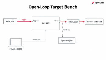
A scenario comes down to a trigger, a delay, a waveform, and a level. Bench basics are in how to use a signal generator. Use these steps to set up a target on the E8267D:
- Define each target's range, velocity, and RCS, along with the radar's carrier, pulse width, PRI, and waveform.
- Connect the radar's sync to the E8267D trigger input and the RF output to the receiver through the planned attenuation.
- Set the carrier and the level from the link budget.
- Build the pulse or chirp (a frequency sweep within the pulse) in N7620B and write the Doppler offset into the I/Q waveform.
- Set the trigger delay for the opening range, then sequence segments for range steps or added targets.
- Add calibrated noise with Option 403 to set a known signal-to-noise ratio (up to 15 MHz of noise bandwidth when added to an arbitrary waveform, so noise does not span a wider chirp).
- Verify level, pulse shape, and the Doppler offset on one of the certified used signal analyzers, which N7620B also uses for waveform corrections, before the receiver sees the signal.
The E8267D is scriptable over LAN or GPIB.
How Do You Use the Same Generator for EW and Threat Simulation?
Threat simulation is the EW counterpart to radar target simulation. The receiver under test is a radar warning receiver (RWR) or electronic support measures (ESM) receiver, and the stimulus is a threat emitter, not a cybersecurity breach test. The same E8267D can drive emitter libraries, interleaved pulse trains, and coherent direction-finding tests:
- Emitter libraries stored as up to 8,192 segments and 16,384 sequences with Option 602.
- Several emitters interleaved in one I/Q waveform, within 80 MHz.
- PDW verification: compare the receiver's pulse descriptor words against the programmed PRI, width, and frequency.
- Coherent multi-source direction finding with Option HCC and the U3035P distribution network.
Keysight Application Note 5992-0094EN puts EW receiver loads at 8 to 10 million pulses per second, with most of the pulse density at X band. It traces one source's pulse density limit to its transition time, pulse width, and lockout period. On the E8267D, frequency switching takes under 16 ms typical (under 24 ms with I/Q on, longer with Option UNY), so pulse-to-pulse carrier hops are not practical. Write frequency changes within the 80 MHz baseband into the I/Q waveform instead.
The 2017 Keysight Application Note 5990-8430EN describes a four-port angle-of-arrival threat simulator built around four E8267D units paired with four 81180A AWGs. The system was designed to hold phase accuracy under 1 degree from 100 MHz to 20 GHz at the end of six-foot test cables. That figure is a system requirement, met with network analyzer correction at the unit under test, not an E8267D data sheet specification. Controlled phase shift between ports creates the simulated angle of arrival.
Keysight Application Note 5992-0094EN sets the minimum for angle-of-arrival work as locking the LOs of multiple sources together so they share the same phase, often with a calibration to align phase and timing. A shared 10 MHz reference alone holds the units' frequency, not their phase. For the E8267D, the data sheet lists the customized options HCC (connections for phase coherency above 250 MHz) and H1G (below 250 MHz), the U3035P distribution network for multiple-source phase coherency, and a baseband generator clock input for sharing a clock between units, so confirm the options on each listing. Keysight Application Note 5992-0839EN explains that most vector signal generators lose phase repeatability when the carrier frequency changes, so recalibrate phase alignment after each retune.
One RF output and 80 MHz of internal bandwidth limit scenario density. Dense multi-port scenarios typically call for a dedicated multi-channel threat simulation system. Direction-finding and monopulse benches typically need two or more E8267D units with matching options, including HCC, so request them together.
Request a Quote on a Certified Used E8267D for Radar and EW Test
Serving radar and EW groups from one bench? Request a quote on a certified used E8267D with both test lists and your coherent unit count.
Which Radar Bands Does a 44 GHz Signal Generator Cover?
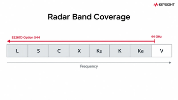
A 2022 Sensors review by Fontana and Di Lauro of the University of Milano-Bicocca lists the IEEE band ranges and calls the S and X bands of great interest for missile defense. Option 544 covers every radar band from L through Ka, and V band from 40 to 44 GHz.
| Band | Nominal range | Coverage | CW power (spec) |
|---|---|---|---|
| L | 1 to 2 GHz | Full | +20 dBm (filters off) |
| S | 2 to 4 GHz | Full | +20 dBm, +14 dBm above 3.2 GHz |
| C | 4 to 8 GHz | Full | +14 dBm |
| X | 8 to 12 GHz | Full | +14 dBm |
| Ku | 12 to 18 GHz | Full | +14 dBm |
| K | 18 to 27 GHz | Full | +14 dBm |
| Ka | 27 to 40 GHz | Full | +14 dBm, +12 dBm above 32 GHz |
| V | 40 to 75 GHz | 40 to 44 GHz | +10 dBm |
Band
Nominal range
Coverage
CW power (spec)
L
Title
1 to 2 GHz
1 to 2 GHz
Title
Full
Full
Title
+20 dBm (filters off)
+20 dBm (filters off)
S
Title
2 to 4 GHz
2 to 4 GHz
Title
Full
Full
Title
+20 dBm, +14 dBm above 3.2 GHz
+20 dBm, +14 dBm above 3.2 GHz
C
Title
4 to 8 GHz
4 to 8 GHz
Title
Full
Full
Title
+14 dBm
+14 dBm
X
Title
8 to 12 GHz
8 to 12 GHz
Title
Full
Full
Title
+14 dBm
+14 dBm
Ku
Title
12 to 18 GHz
12 to 18 GHz
Title
Full
Full
Title
+14 dBm
+14 dBm
K
Title
18 to 27 GHz
18 to 27 GHz
Title
Full
Full
Title
+14 dBm
+14 dBm
Ka
Title
27 to 40 GHz
27 to 40 GHz
Title
Full
Full
Title
+14 dBm, +12 dBm above 32 GHz
+14 dBm, +12 dBm above 32 GHz
V
Title
40 to 75 GHz
40 to 75 GHz
Title
40 to 44 GHz
40 to 44 GHz
Title
+10 dBm
+10 dBm
IEEE Std 521-2026, the radar band letter standard, was approved by the IEEE SA Standards Board on June 4, 2026 and is listed by IEEE as superseding 521-2019, so confirm its band boundaries before a qualification document cites them.
The power column is the CW specification, which applies from 15 to 35 °C. With I/Q modulation through Option 602 it is the same above 3.2 GHz and +17 dBm at 0.4 to 3.2 GHz, and lower through Option 016. Check the link budget at 40 to 44 GHz. Automotive radar at 76 to 81 GHz is above the 44 GHz range of the instrument itself. For band-edge wavelengths, use the wavelength to frequency calculator.
Vector or Analog: When Is an E8257D Enough?
Choose the E8257D for CW and simple pulses, including CW above 44 GHz and specified pulses to 50 GHz. Choose the E8267D when the waveform needs I/Q.
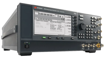
Per Keysight data sheet 5989-0698EN, the E8257D PSG analog signal generator is specified to 67 GHz with Option 567. It offers amplitude, frequency, and phase modulation (Option UNT) and pulse modulation (Option UNU or UNW), but no I/Q modulator. A certified used E8257D PSG analog signal generator can cover pulsed sensitivity (levels below -20 dBm need the Option 1E1 step attenuator, table below), local oscillator (LO) substitution, and component drive above 44 GHz. Check installed options per listing. Chirps, coded pulses, and interleaved emitters built with I/Q need the vector unit, as covered in types of signal generators.
| Capability | E8267D (vector) | E8257D (analog) |
|---|---|---|
| Frequency range | 100 kHz to 44 GHz tunable, specified from 250 kHz (Option 544\) | 100 kHz to 70 GHz tunable, specified to 67 GHz (Option 567\) |
| Minimum settable level | -130 dBm (standard) | -20 dBm standard; -135 dBm with Option 1E1 (-110 dBm with Options 550 and 567\) |
| I/Q modulation | Yes: 80 MHz internal (Option 602); DC to 1.0 GHz external above 3.2 GHz (Option 016\) | No |
| AM, FM, and phase modulation | Option UNT | Option UNT |
| Pulse modulation | Options UNU, UNW | Options UNU, UNW (specified to 50 GHz) |
| Chirps and coded pulses built in I/Q | Yes | No |
| Interleaved emitters in one waveform | Yes, within the modulation bandwidth | No |
| Typical fit | Target returns, EW scenarios | CW, simple pulses, LO, drive above 44 GHz |
Capability
E8267D (vector)
E8257D (analog)
Frequency range
Title
100 kHz to 44 GHz tunable, specified from 250 kHz (Option 544\)
100 kHz to 44 GHz tunable, specified from 250 kHz (Option 544\)
Title
100 kHz to 70 GHz tunable, specified to 67 GHz (Option 567\)
100 kHz to 70 GHz tunable, specified to 67 GHz (Option 567\)
Minimum settable level
Title
-130 dBm (standard)
-130 dBm (standard)
Title
-20 dBm standard; -135 dBm with Option 1E1 (-110 dBm with Options 550 and 567\)
-20 dBm standard; -135 dBm with Option 1E1 (-110 dBm with Options 550 and 567\)
I/Q modulation
Title
Yes: 80 MHz internal (Option 602); DC to 1.0 GHz external above 3.2 GHz (Option 016\)
Yes: 80 MHz internal (Option 602); DC to 1.0 GHz external above 3.2 GHz (Option 016\)
Title
No
No
AM, FM, and phase modulation
Title
Option UNT
Option UNT
Title
Option UNT
Option UNT
Pulse modulation
Title
Options UNU, UNW
Options UNU, UNW
Title
Options UNU, UNW (specified to 50 GHz)
Options UNU, UNW (specified to 50 GHz)
Chirps and coded pulses built in I/Q
Title
Yes
Yes
Title
No
No
Interleaved emitters in one waveform
Title
Yes, within the modulation bandwidth
Yes, within the modulation bandwidth
Title
No
No
Typical fit
Title
Target returns, EW scenarios
Target returns, EW scenarios
Title
CW, simple pulses, LO, drive above 44 GHz
CW, simple pulses, LO, drive above 44 GHz
What Should You Check Before Buying a Certified Used E8267D?
Before you compare prices, start with the option codes on the listing. Then confirm the calibration, warranty, and support behind that exact unit.
Send these with your quote request:
- The highest carrier frequency in your band plan.
- The narrowest pulse width you test.
- The widest waveform bandwidth.
- The number of coherent units.
- The option codes you need: 544, 602, UNW, 016, 403, UNX or UNY, HCC, and the N7620B license. N7620B uses a spectrum or signal analyzer to correct images, flatness, and phase linearity, and the configuration guide lists Option 009 removable memory with it, so confirm both.
- The calibration documents your quality office requires.
Keysight Used equipment comes in working condition, with a 90-day warranty and calibration and accessories as listed. Keysight Premium Used equipment is refurbished at the factory that also manufactures and tests new products, passes the same final test as a new product, and comes with full calibration, the same warranty as a new instrument, and a final 101-point quality check. Up to 5 years of warranty options are available.
Keysight reports that 78% of its customers lose more than $25,000 a day when equipment fails, so weigh KeysightCare and warranty options alongside the price.
Options such as UK6 (commercial certificate with test data) and AMG (accredited calibration) are ordering options on a new instrument. For a used unit, check the calibration listed, and add a fresh calibration or a calibration plan through Keysight calibration services if your quality office needs one.
For procurement, Keysight Used pricing runs 40 to 90% below list price. Keysight Application Note 5992-0839EN calls over-specifying the source a potentially costly mistake when older, less expensive equipment could do the job.
Send your option list and request a quote on a certified used E8267D.
What Does the Data Sheet Leave for Your Bench to Measure?
Measure trigger-to-RF latency once on your bench before you trust a range setting. Data sheet 5989-0697EN gives the external trigger delay as "10 ns to 40 s plus latency", but it does not give a latency figure, so this guide gives none. The nominal 30 ns video-to-RF delay it lists above 3.2 GHz belongs to the pulse modulator path, not the baseband trigger.
Put the trigger on one oscilloscope channel and the detected RF envelope on another. Read the offset at your carrier and pulse settings, then subtract it from every range setting. Scene fidelity for clutter, multipath, and many targets depends on the waveform model your team builds, not on the generator alone.
Request a Quote on Certified Used Microwave Signal Generators
Ready to size the bench? Browse certified used microwave signal generators and request a quote with your option list.
Select up to 3 instruments to compare
Select another instrument to compare
![]()
Starting at
Select another instrument to compare
![]()
Starting at
Select another instrument to compare
![]()
Starting at
A radar target simulator creates a signal that a radar reads as an echo: delayed for range, frequency-shifted for velocity, and scaled for radar cross section. A triggered signal generator can play that return without capturing the radar's pulse.
Radar times the echo's round trip. Range is the speed of light times the delay, divided by 2, which is 6.67 µs per km. Each 10 ns step of E8267D trigger delay (Option 602) moves a simulated target about 1.5 m.
Doppler radar measures the echo's frequency shift. For a closing target, that shift is fd = 2vf/c. A 300 m/s target on a 10 GHz radar shifts the return by about 20 kHz, well inside the E8267D's 80 MHz internal baseband (Option 602).
Radar cross section (RCS) is the effective area, in square meters, that a target presents to the radar. In a bench simulation, RCS becomes an output-level setting. Doubling the range lowers the return by about 12 dB.
An E8267D with Option 602 can simulate multiple targets within limits:
- Several returns in one waveform, within 80 MHz
- Range steps from sequenced segments (up to 8,192)
- Two pulses per trigger in doublet mode (Option UNU or UNW)
Dense scenes typically need more RF outputs.
Many receiver and signal-processor tests run conducted through cables and attenuators, which keeps levels repeatable. Over-the-air setups test the antenna and full system and typically need a chamber, antennas, and a larger link budget.
Target simulation feeds a radar receiver a simulated echo. Threat simulation feeds an EW receiver a simulated emitter. One E8267D can run both. In cybersecurity, "threat simulation" usually means breach and attack testing.
See the Certified Used E8257D for CW up to 67 GHz and Simple Pulses
If your list is CW and simple pulses, or CW above 44 GHz, the certified used E8257D can cover CW to 67 GHz with Option 567 and specified pulses to 50 GHz with Option UNU or UNW, when the listed unit carries them, without I/Q.
Sources
- Keysight data sheet 5989-0697EN, E8267D PSG Vector Signal Generator (July 21, 2023): the E8267D specifications.
- Keysight E8267D product page: product name and option set.
- Keysight data sheet 5989-0698EN, E8257D PSG Analog Signal Generator (June 18, 2025): E8257D range, modulation options (UNT, UNU, UNW), and pulse specifications to 5
- Keysight Application Note 5992-0094EN, Electronic Warfare Signal Generation: Technologies and Methods (February 28, 2026): lab versus flight testing; 8 to 10 million pul
- Keysight Application Note 5992-0544EN, Radar Development Using Model-Based Engineering (October 11, 2020): range and Doppler relationships.
- Keysight Application Note 5989-7575EN, Radar Measurements (March 2, 2020): return proportional to RCS, falling with the fourth power of range.
- Keysight Application Note 5990-8430EN, Creating a Radar Threat Simulator and Receiver Calibrator with Precise Angle of Arrival (December 1, 2017): four-unit E8267D angle
- Keysight Application Note 5992-0839EN, Radar/EW Applications: Choosing the Right Emitter Generation Source (June 7, 2018): AWG-driven I/Q route; over-specification risk.
- Keysight N7624 Signal Studio help, 3. I/Q: E8267D wideband external I/Q, up to 2 GHz RF modulation bandwidth.
- Fontana and Di Lauro, An Overview of Sensors for Long Range Missile Defense, Sensors 22(24):9871 (2022): IEEE band letters and nominal ranges; S and X band interest.
- IEEE Std 521-2026, IEEE Standard Letter Designations for Radar-Frequency Bands (approved June 4, 2026; supersede
- Davis, Georgia Tech Research Institute, Radar Frequencies and Waveforms, NTIA ISART 2011: range resolution against bandwidth.
- Keysight N7620B PathWave Signal Generation for Pulse Building product page: chirps, coded pulses, and pulse-by-pulse phase offsets.
- Keysight N7621B Signal Studio help, Requirements: E8267D Option 601 (8 Msample memory) and Option 602 (64 Msample memory) internal baseband generators.
- Keysight configuration guide 5989-1326EN, E8267D PSG Vector Signal Generator (July 23, 2025): E8267D options, 80 MHz of RF modulation bandwidth with Option
- Keysight N7620B Signal Studio help, Requirements: a spectrum or signal analyzer to measure and correct images, RF flatness, and RF phase linearity.