Learn More
keysight:dtx/solutions/facets/development-area/power,keysight:dtx/solutions/facets/industry/automotive,keysight:dtx/solutions/facets/workflow-stage/conformance-and-compliance,segmentation:campaign/Automotive_Energy,segmentation:product-category/Automotive_Testing,segmentation:product-category/Automotive_Testing/Automotive_Power,segmentation:business-unit/EISG,segmentation:funnel/mofu,keysight:product-lines/ae,keysight:dtx/solutions/facets/design-and-test-product/power-emulator,keysight:dtx/solutions/facets/industry/grid-and-energy,keysight:models/sl/sl1047a,keysight:models/sl/sl2000a,keysight:models/rp/rp7982a,keysight:models/sl/sl1093akeysight:dtx/solutions/facets/development-area/power,keysight:dtx/solutions/facets/industry/automotive,keysight:dtx/solutions/facets/workflow-stage/conformance-and-compliance,segmentation:campaign/Automotive_Energy,segmentation:product-category/Automotive_Testing,segmentation:product-category/Automotive_Testing/Automotive_Power,segmentation:business-unit/EISG,segmentation:funnel/mofu,keysight:product-lines/ae,keysight:dtx/solutions/facets/design-and-test-product/power-emulator,keysight:dtx/solutions/facets/industry/grid-and-energy,keysight:models/sl/sl1047a,keysight:models/sl/sl2000a,keysight:models/rp/rp7982a,keysight:models/sl/sl1093akeysight:dtx/solutions/facets/development-area/power,keysight:dtx/solutions/facets/industry/automotive,keysight:dtx/solutions/facets/workflow-stage/conformance-and-compliance,segmentation:campaign/Automotive_Energy,segmentation:product-category/Automotive_Testing,segmentation:product-category/Automotive_Testing/Automotive_Power,segmentation:business-unit/EISG,segmentation:funnel/mofu,keysight:product-lines/ae,keysight:dtx/solutions/facets/design-and-test-product/power-emulator,keysight:dtx/solutions/facets/industry/grid-and-energy,keysight:models/sl/sl1047a,keysight:models/sl/sl2000a,keysight:models/rp/rp7982a,keysight:models/sl/sl1093akeysight:dtx/solutions/facets/development-area/power,keysight:dtx/solutions/facets/industry/automotive,keysight:dtx/solutions/facets/workflow-stage/conformance-and-compliance,segmentation:campaign/Automotive_Energy,segmentation:product-category/Automotive_Testing,segmentation:product-category/Automotive_Testing/Automotive_Power,segmentation:business-unit/EISG,segmentation:funnel/mofu,keysight:product-lines/ae,keysight:dtx/solutions/facets/design-and-test-product/power-emulator,keysight:dtx/solutions/facets/industry/grid-and-energy,keysight:models/sl/sl1047a,keysight:models/sl/sl2000a,keysight:models/rp/rp7982a,keysight:models/sl/sl1093akeysight:dtx/solutions/facets/development-area/power,keysight:dtx/solutions/facets/industry/automotive,keysight:dtx/solutions/facets/workflow-stage/conformance-and-compliance,segmentation:campaign/Automotive_Energy,segmentation:product-category/Automotive_Testing,segmentation:product-category/Automotive_Testing/Automotive_Power,segmentation:business-unit/EISG,segmentation:funnel/mofu,keysight:product-lines/ae,keysight:dtx/solutions/facets/design-and-test-product/power-emulator,keysight:dtx/solutions/facets/industry/grid-and-energy,keysight:models/sl/sl1047a,keysight:models/sl/sl2000a,keysight:models/rp/rp7982a,keysight:models/sl/sl1093akeysight:dtx/solutions/facets/development-area/power,keysight:dtx/solutions/facets/industry/automotive,keysight:dtx/solutions/facets/workflow-stage/conformance-and-compliance,segmentation:campaign/Automotive_Energy,segmentation:product-category/Automotive_Testing,segmentation:product-category/Automotive_Testing/Automotive_Power,segmentation:business-unit/EISG,segmentation:funnel/mofu,keysight:product-lines/ae,keysight:dtx/solutions/facets/design-and-test-product/power-emulator,keysight:dtx/solutions/facets/industry/grid-and-energy,keysight:models/sl/sl1047a,keysight:models/sl/sl2000a,keysight:models/rp/rp7982a,keysight:models/sl/sl1093akeysight:dtx/solutions/facets/development-area/power,keysight:dtx/solutions/facets/industry/automotive,keysight:dtx/solutions/facets/workflow-stage/conformance-and-compliance,segmentation:campaign/Automotive_Energy,segmentation:product-category/Automotive_Testing,segmentation:product-category/Automotive_Testing/Automotive_Power,segmentation:business-unit/EISG,segmentation:funnel/mofu,keysight:product-lines/ae,keysight:dtx/solutions/facets/design-and-test-product/power-emulator,keysight:dtx/solutions/facets/industry/grid-and-energy,keysight:models/sl/sl1047a,keysight:models/sl/sl2000a,keysight:models/rp/rp7982a,keysight:models/sl/sl1093akeysight:dtx/solutions/facets/development-area/power,keysight:dtx/solutions/facets/industry/automotive,keysight:dtx/solutions/facets/workflow-stage/conformance-and-compliance,segmentation:campaign/Automotive_Energy,segmentation:product-category/Automotive_Testing,segmentation:product-category/Automotive_Testing/Automotive_Power,segmentation:business-unit/EISG,segmentation:funnel/mofu,keysight:product-lines/ae,keysight:dtx/solutions/facets/design-and-test-product/power-emulator,keysight:dtx/solutions/facets/industry/grid-and-energy,keysight:models/sl/sl1047a,keysight:models/sl/sl2000a,keysight:models/rp/rp7982a,keysight:models/sl/sl1093akeysight:dtx/solutions/facets/development-area/power,keysight:dtx/solutions/facets/industry/automotive,keysight:dtx/solutions/facets/workflow-stage/conformance-and-compliance,segmentation:campaign/Automotive_Energy,segmentation:product-category/Automotive_Testing,segmentation:product-category/Automotive_Testing/Automotive_Power,segmentation:business-unit/EISG,segmentation:funnel/mofu,keysight:product-lines/ae,keysight:dtx/solutions/facets/design-and-test-product/power-emulator,keysight:dtx/solutions/facets/industry/grid-and-energy,keysight:models/sl/sl1047a,keysight:models/sl/sl2000a,keysight:models/rp/rp7982a,keysight:models/sl/sl1093akeysight:dtx/solutions/facets/development-area/power,keysight:dtx/solutions/facets/industry/automotive,keysight:dtx/solutions/facets/workflow-stage/conformance-and-compliance,segmentation:campaign/Automotive_Energy,segmentation:product-category/Automotive_Testing,segmentation:product-category/Automotive_Testing/Automotive_Power,segmentation:business-unit/EISG,segmentation:funnel/mofu,keysight:product-lines/ae,keysight:dtx/solutions/facets/design-and-test-product/power-emulator,keysight:dtx/solutions/facets/industry/grid-and-energy,keysight:models/sl/sl1047a,keysight:models/sl/sl2000a,keysight:models/rp/rp7982a,keysight:models/sl/sl1093akeysight:dtx/solutions/facets/development-area/power,keysight:dtx/solutions/facets/industry/automotive,keysight:dtx/solutions/facets/workflow-stage/conformance-and-compliance,segmentation:campaign/Automotive_Energy,segmentation:product-category/Automotive_Testing,segmentation:product-category/Automotive_Testing/Automotive_Power,segmentation:business-unit/EISG,segmentation:funnel/mofu,keysight:product-lines/ae,keysight:dtx/solutions/facets/design-and-test-product/power-emulator,keysight:dtx/solutions/facets/industry/grid-and-energy,keysight:models/sl/sl1047a,keysight:models/sl/sl2000a,keysight:models/rp/rp7982a,keysight:models/sl/sl1093akeysight:dtx/solutions/facets/development-area/power,keysight:dtx/solutions/facets/industry/automotive,keysight:dtx/solutions/facets/workflow-stage/conformance-and-compliance,segmentation:campaign/Automotive_Energy,segmentation:product-category/Automotive_Testing,segmentation:product-category/Automotive_Testing/Automotive_Power,segmentation:business-unit/EISG,segmentation:funnel/mofu,keysight:product-lines/ae,keysight:dtx/solutions/facets/design-and-test-product/power-emulator,keysight:dtx/solutions/facets/industry/grid-and-energy,keysight:models/sl/sl1047a,keysight:models/sl/sl2000a,keysight:models/rp/rp7982a,keysight:models/sl/sl1093akeysight:dtx/solutions/facets/development-area/power,keysight:dtx/solutions/facets/industry/automotive,keysight:dtx/solutions/facets/workflow-stage/conformance-and-compliance,segmentation:campaign/Automotive_Energy,segmentation:product-category/Automotive_Testing,segmentation:product-category/Automotive_Testing/Automotive_Power,segmentation:business-unit/EISG,segmentation:funnel/mofu,keysight:product-lines/ae,keysight:dtx/solutions/facets/design-and-test-product/power-emulator,keysight:dtx/solutions/facets/industry/grid-and-energy,keysight:models/sl/sl1047a,keysight:models/sl/sl2000a,keysight:models/rp/rp7982a,keysight:models/sl/sl1093akeysight:dtx/solutions/facets/development-area/power,keysight:dtx/solutions/facets/industry/automotive,keysight:dtx/solutions/facets/workflow-stage/conformance-and-compliance,segmentation:campaign/Automotive_Energy,segmentation:product-category/Automotive_Testing,segmentation:product-category/Automotive_Testing/Automotive_Power,segmentation:business-unit/EISG,segmentation:funnel/mofu,keysight:product-lines/ae,keysight:dtx/solutions/facets/design-and-test-product/power-emulator,keysight:dtx/solutions/facets/industry/grid-and-energy,keysight:models/sl/sl1047a,keysight:models/sl/sl2000a,keysight:models/rp/rp7982a,keysight:models/sl/sl1093akeysight:dtx/solutions/facets/development-area/power,keysight:dtx/solutions/facets/industry/automotive,keysight:dtx/solutions/facets/workflow-stage/conformance-and-compliance,segmentation:campaign/Automotive_Energy,segmentation:product-category/Automotive_Testing,segmentation:product-category/Automotive_Testing/Automotive_Power,segmentation:business-unit/EISG,segmentation:funnel/mofu,keysight:product-lines/ae,keysight:dtx/solutions/facets/design-and-test-product/power-emulator,keysight:dtx/solutions/facets/industry/grid-and-energy,keysight:models/sl/sl1047a,keysight:models/sl/sl2000a,keysight:models/rp/rp7982a,keysight:models/sl/sl1093a
How to Verify EVSE Charging Conformance
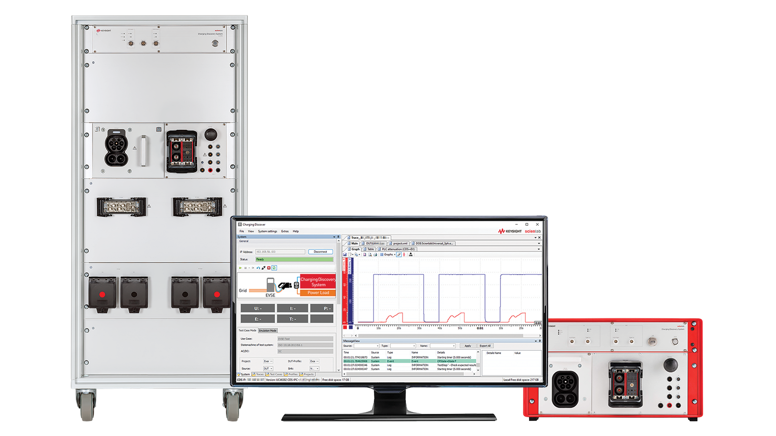
Validating electric vehicle (EV) supply equipment requires verifying its conformance to worldwide standards and interoperability with different EV models on the market. Learn how to set up a test to emulate an EV and configure it for various specifications to test your EV supply equipment.
Learn More