Learn More
keysight:dtx/solutions/facets/development-area/high-speed-digital,keysight:dtx/solutions/facets/design-and-test-product/oscilloscope---logic-analyzer,keysight:dtx/solutions/facets/industry/wireline-communications,segmentation:campaign/Digital_General_Purpose,keysight:product-lines/1a,segmentation:business-unit/CSG,segmentation:product-category/Oscilloscopes_BERTs_AWGs,segmentation:product-category/Oscilloscopes_BERTs_AWGs/Oscilloscopes_2GHz_higher,segmentation:funnel/bofu,keysight:dtx/solutions/facets/workflow-stage/functional-test,keysight:models/mx/mxr054a,keysight:models/d9/d9010embp,keysight:models/n7/n7020a,keysight:models/n7/n7019a,keysight:models/d9/d9010asia,keysight:models/d9/d9010powa,keysight:models/mx/mxr058bkeysight:dtx/solutions/facets/development-area/high-speed-digital,keysight:dtx/solutions/facets/design-and-test-product/oscilloscope---logic-analyzer,keysight:dtx/solutions/facets/industry/wireline-communications,segmentation:campaign/Digital_General_Purpose,keysight:product-lines/1a,segmentation:business-unit/CSG,segmentation:product-category/Oscilloscopes_BERTs_AWGs,segmentation:product-category/Oscilloscopes_BERTs_AWGs/Oscilloscopes_2GHz_higher,segmentation:funnel/bofu,keysight:dtx/solutions/facets/workflow-stage/functional-test,keysight:models/mx/mxr054a,keysight:models/d9/d9010embp,keysight:models/n7/n7020a,keysight:models/n7/n7019a,keysight:models/d9/d9010asia,keysight:models/d9/d9010powa,keysight:models/mx/mxr058bkeysight:dtx/solutions/facets/development-area/high-speed-digital,keysight:dtx/solutions/facets/design-and-test-product/oscilloscope---logic-analyzer,keysight:dtx/solutions/facets/industry/wireline-communications,segmentation:campaign/Digital_General_Purpose,keysight:product-lines/1a,segmentation:business-unit/CSG,segmentation:product-category/Oscilloscopes_BERTs_AWGs,segmentation:product-category/Oscilloscopes_BERTs_AWGs/Oscilloscopes_2GHz_higher,segmentation:funnel/bofu,keysight:dtx/solutions/facets/workflow-stage/functional-test,keysight:models/mx/mxr054a,keysight:models/d9/d9010embp,keysight:models/n7/n7020a,keysight:models/n7/n7019a,keysight:models/d9/d9010asia,keysight:models/d9/d9010powa,keysight:models/mx/mxr058bkeysight:dtx/solutions/facets/development-area/high-speed-digital,keysight:dtx/solutions/facets/design-and-test-product/oscilloscope---logic-analyzer,keysight:dtx/solutions/facets/industry/wireline-communications,segmentation:campaign/Digital_General_Purpose,keysight:product-lines/1a,segmentation:business-unit/CSG,segmentation:product-category/Oscilloscopes_BERTs_AWGs,segmentation:product-category/Oscilloscopes_BERTs_AWGs/Oscilloscopes_2GHz_higher,segmentation:funnel/bofu,keysight:dtx/solutions/facets/workflow-stage/functional-test,keysight:models/mx/mxr054a,keysight:models/d9/d9010embp,keysight:models/n7/n7020a,keysight:models/n7/n7019a,keysight:models/d9/d9010asia,keysight:models/d9/d9010powa,keysight:models/mx/mxr058bkeysight:dtx/solutions/facets/development-area/high-speed-digital,keysight:dtx/solutions/facets/design-and-test-product/oscilloscope---logic-analyzer,keysight:dtx/solutions/facets/industry/wireline-communications,segmentation:campaign/Digital_General_Purpose,keysight:product-lines/1a,segmentation:business-unit/CSG,segmentation:product-category/Oscilloscopes_BERTs_AWGs,segmentation:product-category/Oscilloscopes_BERTs_AWGs/Oscilloscopes_2GHz_higher,segmentation:funnel/bofu,keysight:dtx/solutions/facets/workflow-stage/functional-test,keysight:models/mx/mxr054a,keysight:models/d9/d9010embp,keysight:models/n7/n7020a,keysight:models/n7/n7019a,keysight:models/d9/d9010asia,keysight:models/d9/d9010powa,keysight:models/mx/mxr058bkeysight:dtx/solutions/facets/development-area/high-speed-digital,keysight:dtx/solutions/facets/design-and-test-product/oscilloscope---logic-analyzer,keysight:dtx/solutions/facets/industry/wireline-communications,segmentation:campaign/Digital_General_Purpose,keysight:product-lines/1a,segmentation:business-unit/CSG,segmentation:product-category/Oscilloscopes_BERTs_AWGs,segmentation:product-category/Oscilloscopes_BERTs_AWGs/Oscilloscopes_2GHz_higher,segmentation:funnel/bofu,keysight:dtx/solutions/facets/workflow-stage/functional-test,keysight:models/mx/mxr054a,keysight:models/d9/d9010embp,keysight:models/n7/n7020a,keysight:models/n7/n7019a,keysight:models/d9/d9010asia,keysight:models/d9/d9010powa,keysight:models/mx/mxr058bkeysight:dtx/solutions/facets/development-area/high-speed-digital,keysight:dtx/solutions/facets/design-and-test-product/oscilloscope---logic-analyzer,keysight:dtx/solutions/facets/industry/wireline-communications,segmentation:campaign/Digital_General_Purpose,keysight:product-lines/1a,segmentation:business-unit/CSG,segmentation:product-category/Oscilloscopes_BERTs_AWGs,segmentation:product-category/Oscilloscopes_BERTs_AWGs/Oscilloscopes_2GHz_higher,segmentation:funnel/bofu,keysight:dtx/solutions/facets/workflow-stage/functional-test,keysight:models/mx/mxr054a,keysight:models/d9/d9010embp,keysight:models/n7/n7020a,keysight:models/n7/n7019a,keysight:models/d9/d9010asia,keysight:models/d9/d9010powa,keysight:models/mx/mxr058bkeysight:dtx/solutions/facets/development-area/high-speed-digital,keysight:dtx/solutions/facets/design-and-test-product/oscilloscope---logic-analyzer,keysight:dtx/solutions/facets/industry/wireline-communications,segmentation:campaign/Digital_General_Purpose,keysight:product-lines/1a,segmentation:business-unit/CSG,segmentation:product-category/Oscilloscopes_BERTs_AWGs,segmentation:product-category/Oscilloscopes_BERTs_AWGs/Oscilloscopes_2GHz_higher,segmentation:funnel/bofu,keysight:dtx/solutions/facets/workflow-stage/functional-test,keysight:models/mx/mxr054a,keysight:models/d9/d9010embp,keysight:models/n7/n7020a,keysight:models/n7/n7019a,keysight:models/d9/d9010asia,keysight:models/d9/d9010powa,keysight:models/mx/mxr058bkeysight:dtx/solutions/facets/development-area/high-speed-digital,keysight:dtx/solutions/facets/design-and-test-product/oscilloscope---logic-analyzer,keysight:dtx/solutions/facets/industry/wireline-communications,segmentation:campaign/Digital_General_Purpose,keysight:product-lines/1a,segmentation:business-unit/CSG,segmentation:product-category/Oscilloscopes_BERTs_AWGs,segmentation:product-category/Oscilloscopes_BERTs_AWGs/Oscilloscopes_2GHz_higher,segmentation:funnel/bofu,keysight:dtx/solutions/facets/workflow-stage/functional-test,keysight:models/mx/mxr054a,keysight:models/d9/d9010embp,keysight:models/n7/n7020a,keysight:models/n7/n7019a,keysight:models/d9/d9010asia,keysight:models/d9/d9010powa,keysight:models/mx/mxr058bkeysight:dtx/solutions/facets/development-area/high-speed-digital,keysight:dtx/solutions/facets/design-and-test-product/oscilloscope---logic-analyzer,keysight:dtx/solutions/facets/industry/wireline-communications,segmentation:campaign/Digital_General_Purpose,keysight:product-lines/1a,segmentation:business-unit/CSG,segmentation:product-category/Oscilloscopes_BERTs_AWGs,segmentation:product-category/Oscilloscopes_BERTs_AWGs/Oscilloscopes_2GHz_higher,segmentation:funnel/bofu,keysight:dtx/solutions/facets/workflow-stage/functional-test,keysight:models/mx/mxr054a,keysight:models/d9/d9010embp,keysight:models/n7/n7020a,keysight:models/n7/n7019a,keysight:models/d9/d9010asia,keysight:models/d9/d9010powa,keysight:models/mx/mxr058bkeysight:dtx/solutions/facets/development-area/high-speed-digital,keysight:dtx/solutions/facets/design-and-test-product/oscilloscope---logic-analyzer,keysight:dtx/solutions/facets/industry/wireline-communications,segmentation:campaign/Digital_General_Purpose,keysight:product-lines/1a,segmentation:business-unit/CSG,segmentation:product-category/Oscilloscopes_BERTs_AWGs,segmentation:product-category/Oscilloscopes_BERTs_AWGs/Oscilloscopes_2GHz_higher,segmentation:funnel/bofu,keysight:dtx/solutions/facets/workflow-stage/functional-test,keysight:models/mx/mxr054a,keysight:models/d9/d9010embp,keysight:models/n7/n7020a,keysight:models/n7/n7019a,keysight:models/d9/d9010asia,keysight:models/d9/d9010powa,keysight:models/mx/mxr058bkeysight:dtx/solutions/facets/development-area/high-speed-digital,keysight:dtx/solutions/facets/design-and-test-product/oscilloscope---logic-analyzer,keysight:dtx/solutions/facets/industry/wireline-communications,segmentation:campaign/Digital_General_Purpose,keysight:product-lines/1a,segmentation:business-unit/CSG,segmentation:product-category/Oscilloscopes_BERTs_AWGs,segmentation:product-category/Oscilloscopes_BERTs_AWGs/Oscilloscopes_2GHz_higher,segmentation:funnel/bofu,keysight:dtx/solutions/facets/workflow-stage/functional-test,keysight:models/mx/mxr054a,keysight:models/d9/d9010embp,keysight:models/n7/n7020a,keysight:models/n7/n7019a,keysight:models/d9/d9010asia,keysight:models/d9/d9010powa,keysight:models/mx/mxr058bkeysight:dtx/solutions/facets/development-area/high-speed-digital,keysight:dtx/solutions/facets/design-and-test-product/oscilloscope---logic-analyzer,keysight:dtx/solutions/facets/industry/wireline-communications,segmentation:campaign/Digital_General_Purpose,keysight:product-lines/1a,segmentation:business-unit/CSG,segmentation:product-category/Oscilloscopes_BERTs_AWGs,segmentation:product-category/Oscilloscopes_BERTs_AWGs/Oscilloscopes_2GHz_higher,segmentation:funnel/bofu,keysight:dtx/solutions/facets/workflow-stage/functional-test,keysight:models/mx/mxr054a,keysight:models/d9/d9010embp,keysight:models/n7/n7020a,keysight:models/n7/n7019a,keysight:models/d9/d9010asia,keysight:models/d9/d9010powa,keysight:models/mx/mxr058bkeysight:dtx/solutions/facets/development-area/high-speed-digital,keysight:dtx/solutions/facets/design-and-test-product/oscilloscope---logic-analyzer,keysight:dtx/solutions/facets/industry/wireline-communications,segmentation:campaign/Digital_General_Purpose,keysight:product-lines/1a,segmentation:business-unit/CSG,segmentation:product-category/Oscilloscopes_BERTs_AWGs,segmentation:product-category/Oscilloscopes_BERTs_AWGs/Oscilloscopes_2GHz_higher,segmentation:funnel/bofu,keysight:dtx/solutions/facets/workflow-stage/functional-test,keysight:models/mx/mxr054a,keysight:models/d9/d9010embp,keysight:models/n7/n7020a,keysight:models/n7/n7019a,keysight:models/d9/d9010asia,keysight:models/d9/d9010powa,keysight:models/mx/mxr058bkeysight:dtx/solutions/facets/development-area/high-speed-digital,keysight:dtx/solutions/facets/design-and-test-product/oscilloscope---logic-analyzer,keysight:dtx/solutions/facets/industry/wireline-communications,segmentation:campaign/Digital_General_Purpose,keysight:product-lines/1a,segmentation:business-unit/CSG,segmentation:product-category/Oscilloscopes_BERTs_AWGs,segmentation:product-category/Oscilloscopes_BERTs_AWGs/Oscilloscopes_2GHz_higher,segmentation:funnel/bofu,keysight:dtx/solutions/facets/workflow-stage/functional-test,keysight:models/mx/mxr054a,keysight:models/d9/d9010embp,keysight:models/n7/n7020a,keysight:models/n7/n7019a,keysight:models/d9/d9010asia,keysight:models/d9/d9010powa,keysight:models/mx/mxr058bkeysight:dtx/solutions/facets/development-area/high-speed-digital,keysight:dtx/solutions/facets/design-and-test-product/oscilloscope---logic-analyzer,keysight:dtx/solutions/facets/industry/wireline-communications,segmentation:campaign/Digital_General_Purpose,keysight:product-lines/1a,segmentation:business-unit/CSG,segmentation:product-category/Oscilloscopes_BERTs_AWGs,segmentation:product-category/Oscilloscopes_BERTs_AWGs/Oscilloscopes_2GHz_higher,segmentation:funnel/bofu,keysight:dtx/solutions/facets/workflow-stage/functional-test,keysight:models/mx/mxr054a,keysight:models/d9/d9010embp,keysight:models/n7/n7020a,keysight:models/n7/n7019a,keysight:models/d9/d9010asia,keysight:models/d9/d9010powa,keysight:models/mx/mxr058bkeysight:dtx/solutions/facets/development-area/high-speed-digital,keysight:dtx/solutions/facets/design-and-test-product/oscilloscope---logic-analyzer,keysight:dtx/solutions/facets/industry/wireline-communications,segmentation:campaign/Digital_General_Purpose,keysight:product-lines/1a,segmentation:business-unit/CSG,segmentation:product-category/Oscilloscopes_BERTs_AWGs,segmentation:product-category/Oscilloscopes_BERTs_AWGs/Oscilloscopes_2GHz_higher,segmentation:funnel/bofu,keysight:dtx/solutions/facets/workflow-stage/functional-test,keysight:models/mx/mxr054a,keysight:models/d9/d9010embp,keysight:models/n7/n7020a,keysight:models/n7/n7019a,keysight:models/d9/d9010asia,keysight:models/d9/d9010powa,keysight:models/mx/mxr058b
How to Test USB Type-C Power Delivery
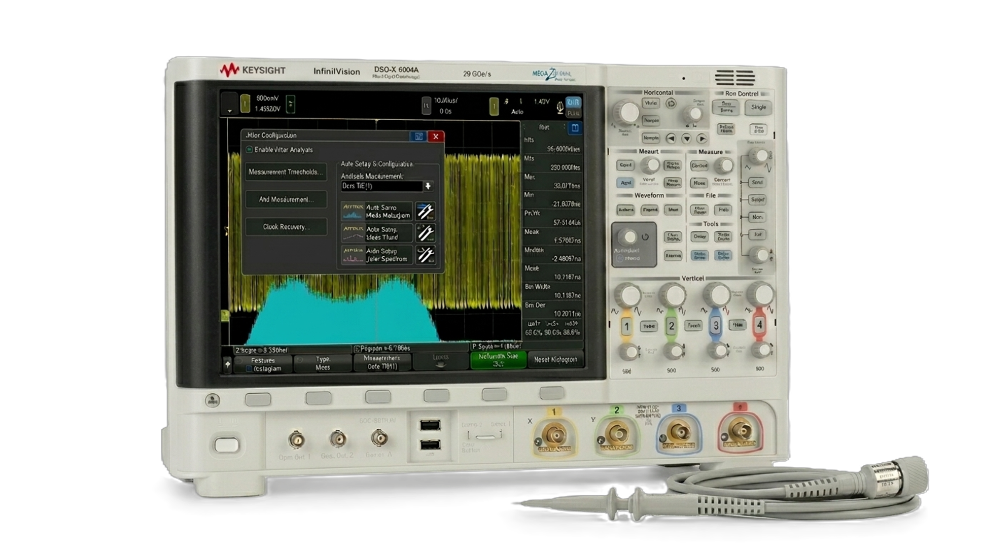
Testing the USB Type-C power delivery module requires monitoring the CC lines with a 300 kHz signal and measuring the generated voltage and currents. Learn how you can analyze the resulting eye diagram with an oscilloscope to ensure the dynamically variable power provided by USB Type-C power delivery achieve compliance.
Learn More