
M8091BMCA Receiver Conformance Test Application for IEEE 802.3bm
Data Sheets
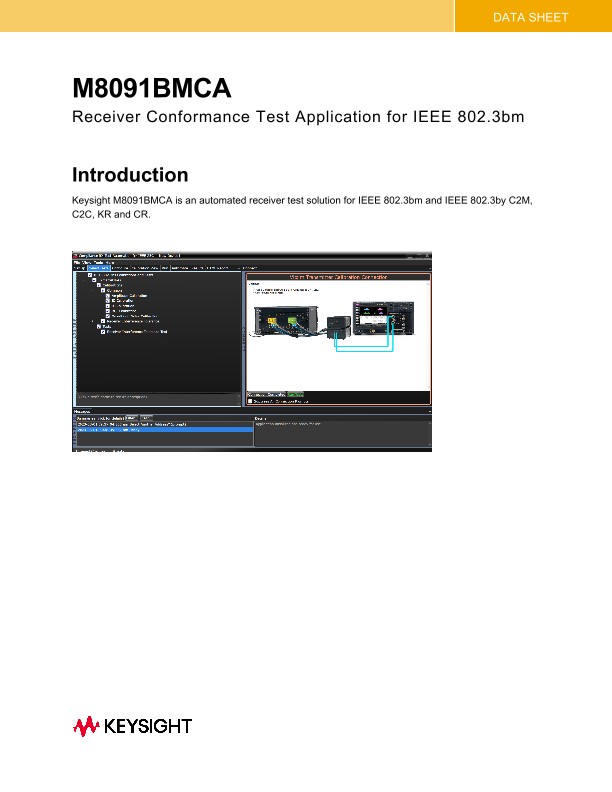
Introduction
Keysight M8091BMCA is an automated receiver test solution for IEEE 802.3bm and IEEE 802.3by C2M, C2C, KR and CR.
Key Features
• Supported standards include the following:
o IEEE 802.3by Chip-to-module 25 Gigabit Attachment Unit Interface (25GAUI C2M) Annex 109B1
- 109B.3.3 25GAUI C2M host input characteristics
- 109B.3.4 25GAUI C2M module input characteristics
o IEEE 802.3by Chip-to-chip 25 Gigabit Attachment Unit Interface (25GAUI C2C), Annex 109A2
- 109A.3.2 25GAUI C2C receiver characteristics
o Clause 110. Physical Medium Dependent (PMD) sublayer and baseband medium, type 25GBASE-CR and 25GBASE-CR-S3
- Clause 110.8.4.1 Receiver input amplitude tolerance
- Clause 110.8.4.2 Receiver interference tolerance test
o Clause 111. Physical Medium Dependent (PMD) sublayer and baseband medium, type 25GBASE-KR and 25GBASE-KR-S4
- 111.8.3.1 Receiver interference tolerance
- 111.8.3.2 Receiver jitter tolerance
• Guided setup, automated stress signal calibration and conformance measurement
• HTML test report
• Data analytics enabled
• Choose between Node-locked, Transportable, Network, USB-dongle license types of the Perpetual License Term
Description
The Keysight M8091BMCA receiver conformance test application is designed to assist and simplify the stress signal calibration used for testing the inputs of CAUI-4 C2M (host and module) CAUI-4 C2C, KR and CR.
The conformance application provides a user interface menu with the flexibility to choose compliance or debug mode. It reduces user interaction to a minimum and performs all required calibration routines and compliance testing automatically by remote controlling all required instruments. A wide range of hardware configurations is supported, thus protecting your investment.
The test application utilizes the same framework for the graphical user interface like most Keysight transmitter applications reducing training time by providing a common look and feel. When a user is required to perform setup changes, the user is guided by diagrams as well as text to minimize errors. Results of the individual calibration steps and tests are presented in tabular form as well as graphical form, where appropriate. Calibrations and test results can be stored in projects and recalled at a later point in time. The application can generate an HTML-based test report.
Calibrations and Tests Covered by M8091BMCA Receiver
CAUI-4 C2M (host and module)
The chip-to-module (C2M) interface provides electrical characteristics and associated compliance points, which can be used to design systems with pluggable module interfaces. The 25GBASE C2M interface is based on a 25.78125 NRZ. The chip-to-module interface is defined using a specification and test methodology that is similar to that used for CEI-28G-VSR defined in OIF-CEI.
Testing C2M interfaces requires reference test fixtures, called compliance boards: Host Compliance Board (HCB) is used to access the host chip and the Module Compliance Board (MCB) is used to access the module chip. When connected together (“mated test fixtures”) the resulting channel is expected to be close to a compliant channel between the host and module chips. (fig 4). QSFP and SFP+ test fixtures are common for 25G and CAUI-4 interfaces.
Keysight M8091BMCA Compliance Receiver Test Application provides the following calibrations and tests for 25GBASE C2M Host and Module following
• clause 109B.3.3 (83E.3.3.2, Host stressed input test) for the host input test
• clause 109B.3.4 (83E.3.4.1, Module stressed input test) for the module input test.
Calibration:
• Crosstalk Amplitude and Transition Time
• Amplitude
• Sinusoidal Jitter (SJ)
• Random and total Jitter (TJ, RJ)
• Stressed Eye
Tests:
• Stressed Input
• Voltage Tolerance
• Voltage tolerance
Example setup for C2M Host input stress eye calibration
• Connect MCB and HCB
• Connect the X-Talk Generator's Data Out 2 P/N to TP1 P/N of MCB
• Terminate the TP1a P/N of HCB with 50 ohms
• Connect the Victim Generator's Data Out 1 P/N to TP4a P/N of HCB
• Connect the MCB TP4 P/N to Oscilloscope's Ch1/2 via Pick-Off
• Connect the Data for clock recovery from Pick-Off
25GBASE-C2C, 25GBASE-KR, 25GBASE-CR
The chip-to-chip (C2C), backplane (KR) and copper (CR) interface provides electrical characteristics and associated compliance points, which can be used to design SerDes interconnects. The target applications are listed in the table below.
Testing C2C and KR interfaces requires a trace board acting as a test channel combined with a coupler (for interference injection) to be tested. In addition, CR interfaces requires reference test fixtures: the Host Compliance Board (HCB) is used to access the host chip, while a Module Compliance Board (MCB) can used to inject the stress signal into the test channel when a copper cable instead of a trace board is used (fig 7). QSFP and SFP+ test fixtures are common for 25G and CAUI-4 interfaces. The C2C, KR and CR interfaces are tested using the channel operating margin (COM) methodology defined in the IEEE 802.3 Annex 93A. Note that Link Training as defined in 92.7.12 isn’t used to optimize the transmitter equalizer coefficients to the device under test for CR and KR tests. Instead, the transmitter equalization (TX EQ) is based on the COM analysis and can be adjusted manually if required.