How to Select the Right Diode Power Sensor for RF Measurements

Select the Right Diode Sensor
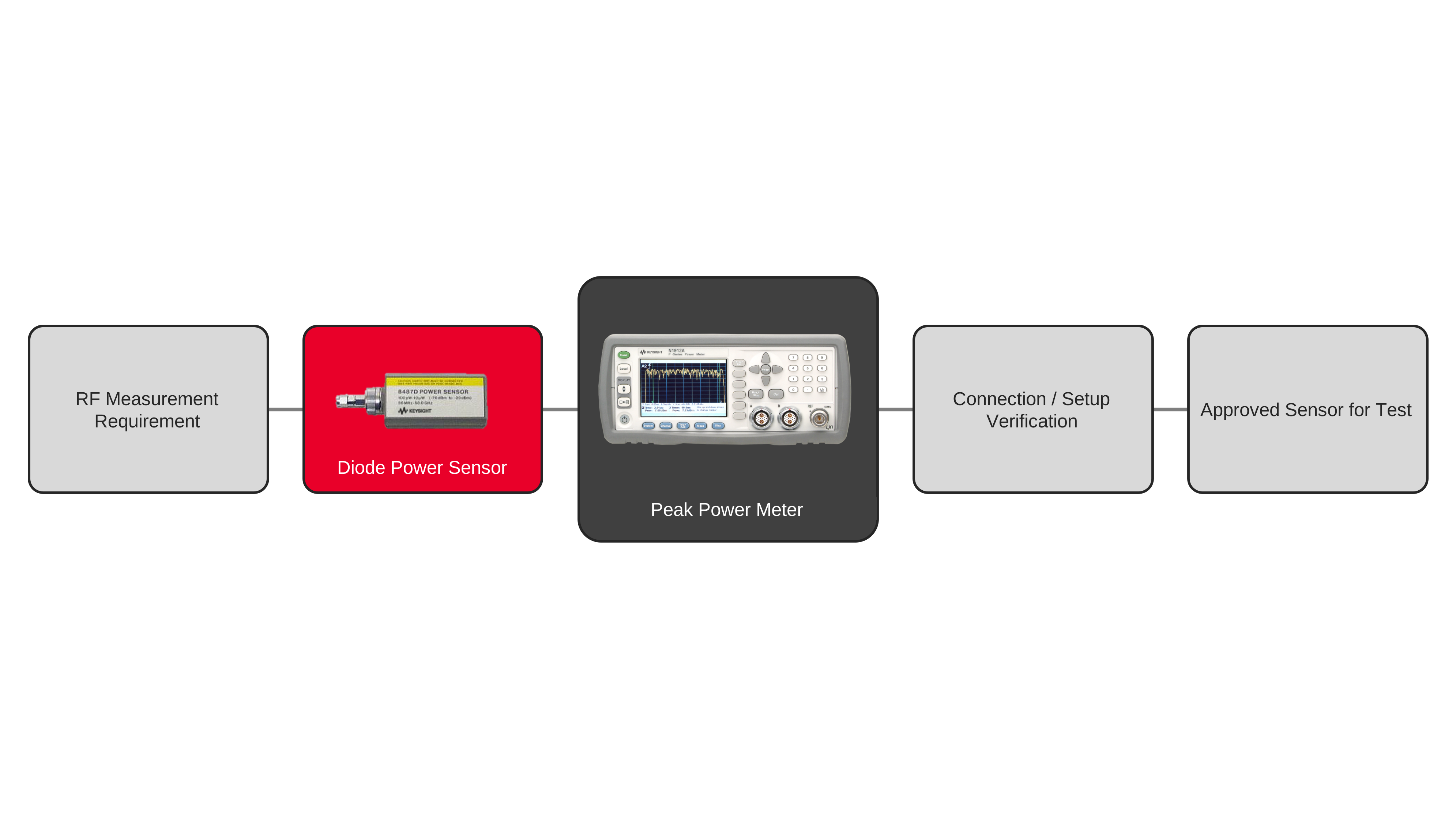
Selecting the right diode power sensor for radio frequency measurements requires matching the sensor’s frequency range, power range, response characteristics, and connector interface to the intended test application. Engineers evaluate whether the signal is continuous-wave (CW), modulated, or otherwise steady enough to benefit from diode sensor response behavior, then compare the expected power level and operating frequency against the sensor’s measurement limits. The measurement setup typically includes a peak power meter, diode power sensor, and appropriate interconnects so the sensor can be used without excessive loss or mismatch at the measurement plane. Proper selection helps ensure that the sensor can provide accurate readings for the signal type and operating conditions under test.
The sensor choice also depends on how quickly measurements must be made and how much test throughput is required. Engineers often review sensor characteristics such as response speed, dynamic range, and compatibility with the meter interface before configuring the measurement setup. During development and manufacturing, the selected sensor must support repeatable measurements across the expected range of operating conditions while remaining straightforward to connect and verify. A well-matched diode power sensor simplifies measurement setup, reduces unnecessary settling time, and helps ensure that the resulting data reflects the actual radio frequency power present at the device under test.

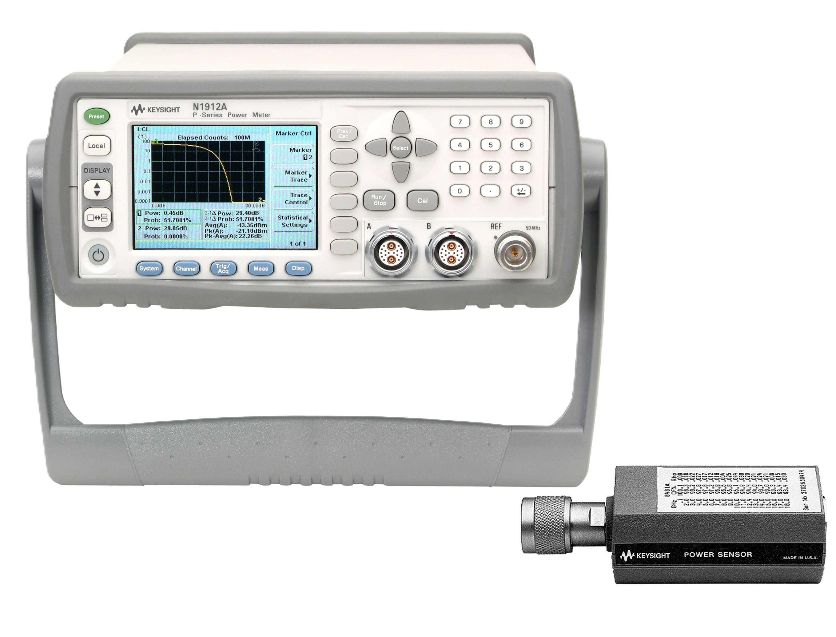
Diode Power Sensor Selection Solution
See Block Diagram of Diode Power Sensor Selection Solution

Explore Products for Our Diode Power Sensor Selection Solution
-

![]()
N1912A P-Series Dual Channel Power Meter
-
![]()
8487D Diode Power Sensor


Discover Resources and Insights
Additional Resources for Diode Power Sensor Selection
Related Use Cases

-
![]()
Learn More
How to Perform Burst Power Measurement
Measure burst RF signal power using time-gated averaging with power meters, sensors, and automated control software for TDMA systems.
Learn More

-
![]()
Learn More
How to Measure RF Power During Rapid Amplitude Switching
Measure RF power during rapid amplitude transitions using a power meter, fast-response sensors, continuous acquisition, and automated measurement techniques.
Learn More
-
![]()
Learn More
How to Measure Average Power of Frequency-Hopping Signals
Measure average RF power of frequency-hopping signals using power meters, sensors, and time-aligned measurement techniques for accurate results.
Learn More

Get in Touch with One of Our Experts
Need help finding the right solution for you?