How to Prevent Diode Power Sensor Damage During RF Testing

Protect Diode Power Sensors
Preventing damage to diode power sensors requires understanding the operating limits of the measurement system before connecting the sensor to a radio frequency source. Engineers must consider continuous-wave power, peak power, pulse characteristics, frequency range, connector condition, and impedance matching to ensure that the sensor is not exposed to excessive energy. Unexpected signal levels, poor connection practices, electrostatic discharge, or improper handling can permanently damage sensitive measurement components or reduce measurement accuracy over time. Careful verification of source conditions and proper measurement setup help minimize the risk of sensor failure during development, validation, and manufacturing activities.
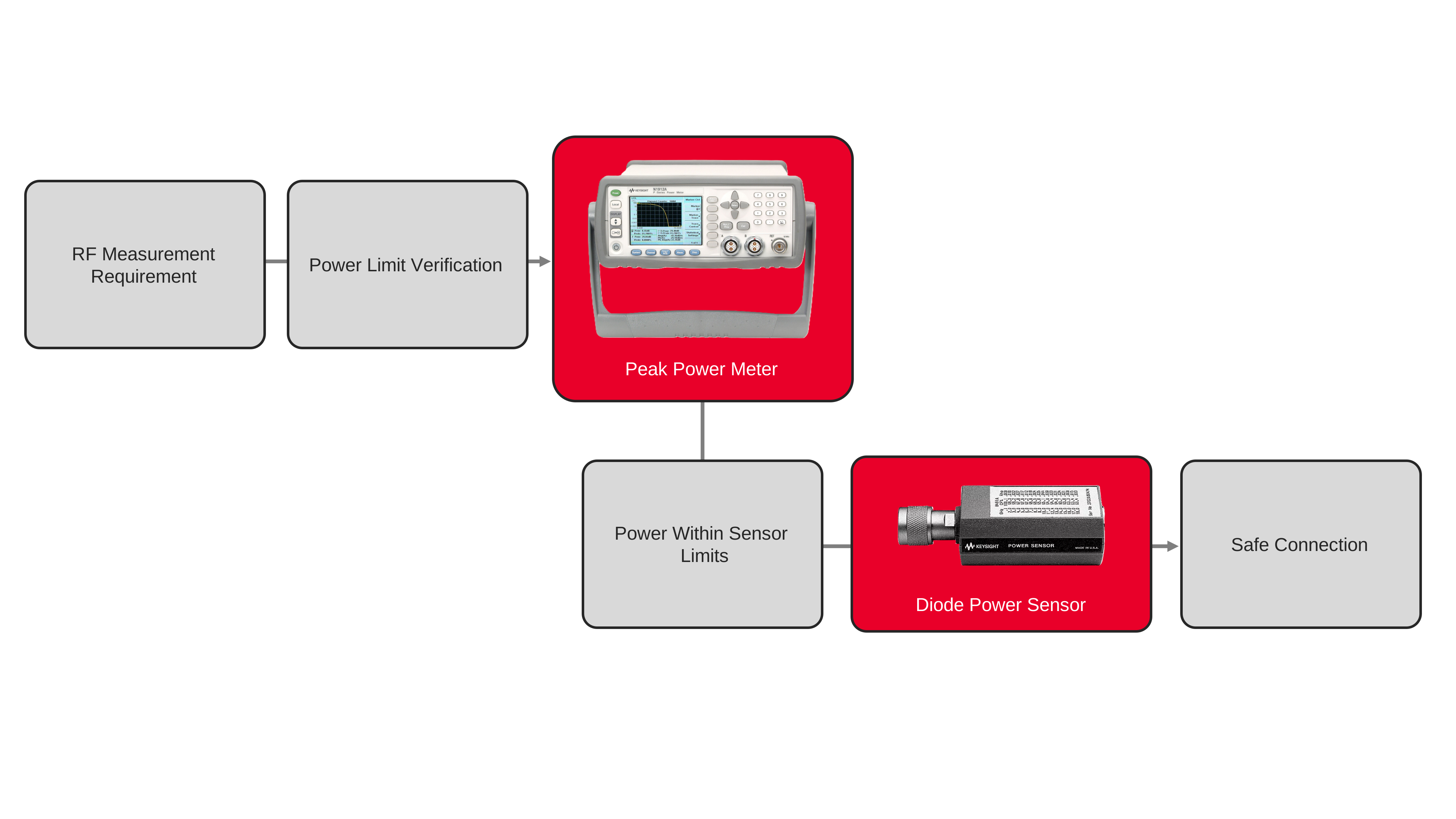
The measurement configuration typically includes a diode power sensor, a compatible peak power meter, and appropriate RF interconnects for the application. Engineers verify source power levels before connection, inspect connectors for contamination or damage, and follow recommended handling procedures throughout the measurement process. Routine inspection, proper connection techniques, and operation within specified measurement limits help preserve sensor performance while reducing unexpected downtime, measurement uncertainty, and replacement costs associated with damaged RF power sensors.

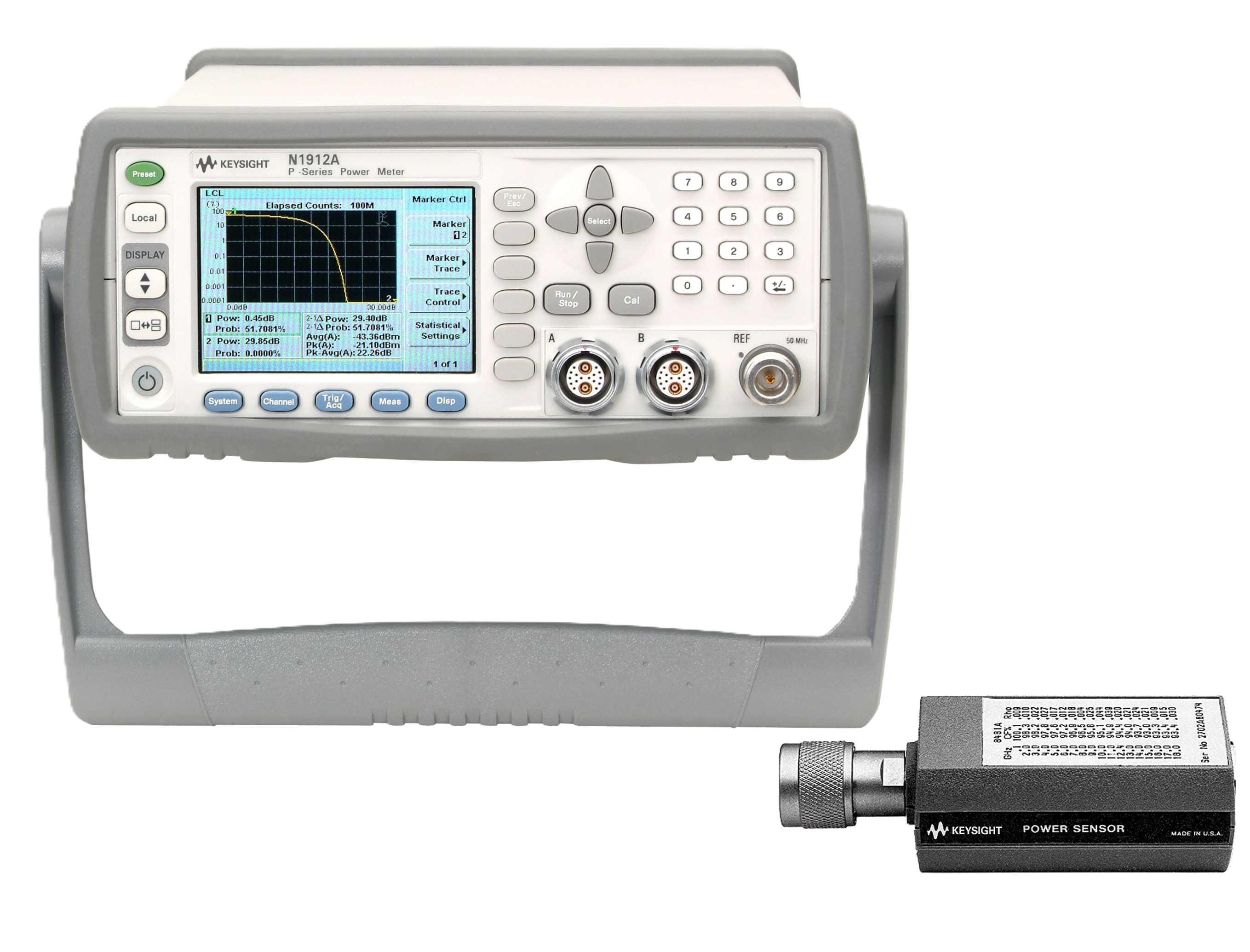
Diode Power Sensor Protection Solution
See Block Diagram of Diode Power Sensor Protection Solution

Explore Products in Our Diode Power Sensor Protection Solution
-

![]()
N1912A P-Series Dual Channel Power Meter
-
![]()
8487D Diode Power Sensor


Discover Resources and Insights
Additional Resources for Diode Power Sensor Protection
Related Use Cases

-
![]()
Learn More
How to Perform Burst Power Measurement
Measure burst RF signal power using time-gated averaging with power meters, sensors, and automated control software for TDMA systems.
Learn More

-
![]()
Learn More
How to Measure RF Power During Rapid Amplitude Switching
Measure RF power during rapid amplitude transitions using a power meter, fast-response sensors, continuous acquisition, and automated measurement techniques.
Learn More
-
![]()
Learn More
How to Measure Average Power of Frequency-Hopping Signals
Measure average RF power of frequency-hopping signals using power meters, sensors, and time-aligned measurement techniques for accurate results.
Learn More

Get in Touch with One of Our Experts
Need help finding the right solution for you?