How to Measure Amplifier Gain Compression and P1dB

Amplifier Gain Solution
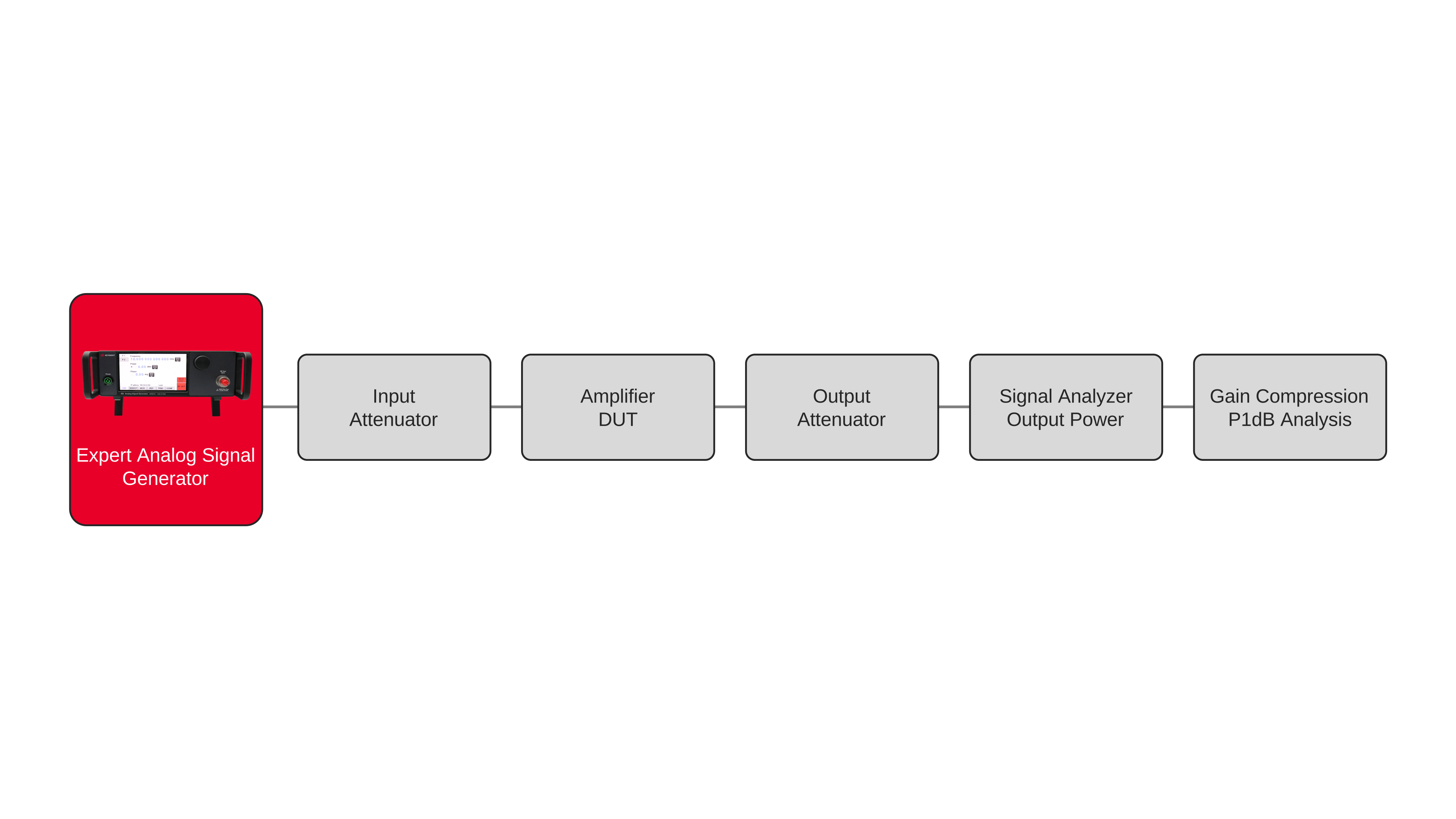
Measuring amplifier gain compression and the 1 dB compression point (P1dB) requires a calibrated RF stimulus with controlled frequency and power, along with an instrument capable of accurately measuring the amplifier output level. Engineers first establish the amplifier’s small-signal gain by applying an RF input at a power level within the linear operating region and measuring the corresponding output power. The input power is then increased in controlled steps while the output power is monitored with a signal analyzer or power sensor. As long as the amplifier remains linear, changes in output power closely track changes in input power and the calculated gain remains relatively constant. Accurate source power, stable frequency, and repeatable power stepping help maintain consistent measurement conditions throughout the sweep.
As the RF input level continues to increase, amplifier nonlinearities cause the output response to deviate from the expected linear relationship. Engineers calculate gain at each input power level and compare it with the established small-signal gain to determine the amount of compression. The 1 dB compression point is reached when the measured gain decreases by 1 dB relative to the linear gain response. Depending on the required reference plane, P1dB can be reported as either input power or output power. Repeating the measurement across frequency provides amplifier gain compression and P1dB characterization over the required operating range. The same measurement sequence can also be repeated under different amplifier bias, temperature, or operating conditions to evaluate changes in compression behavior.

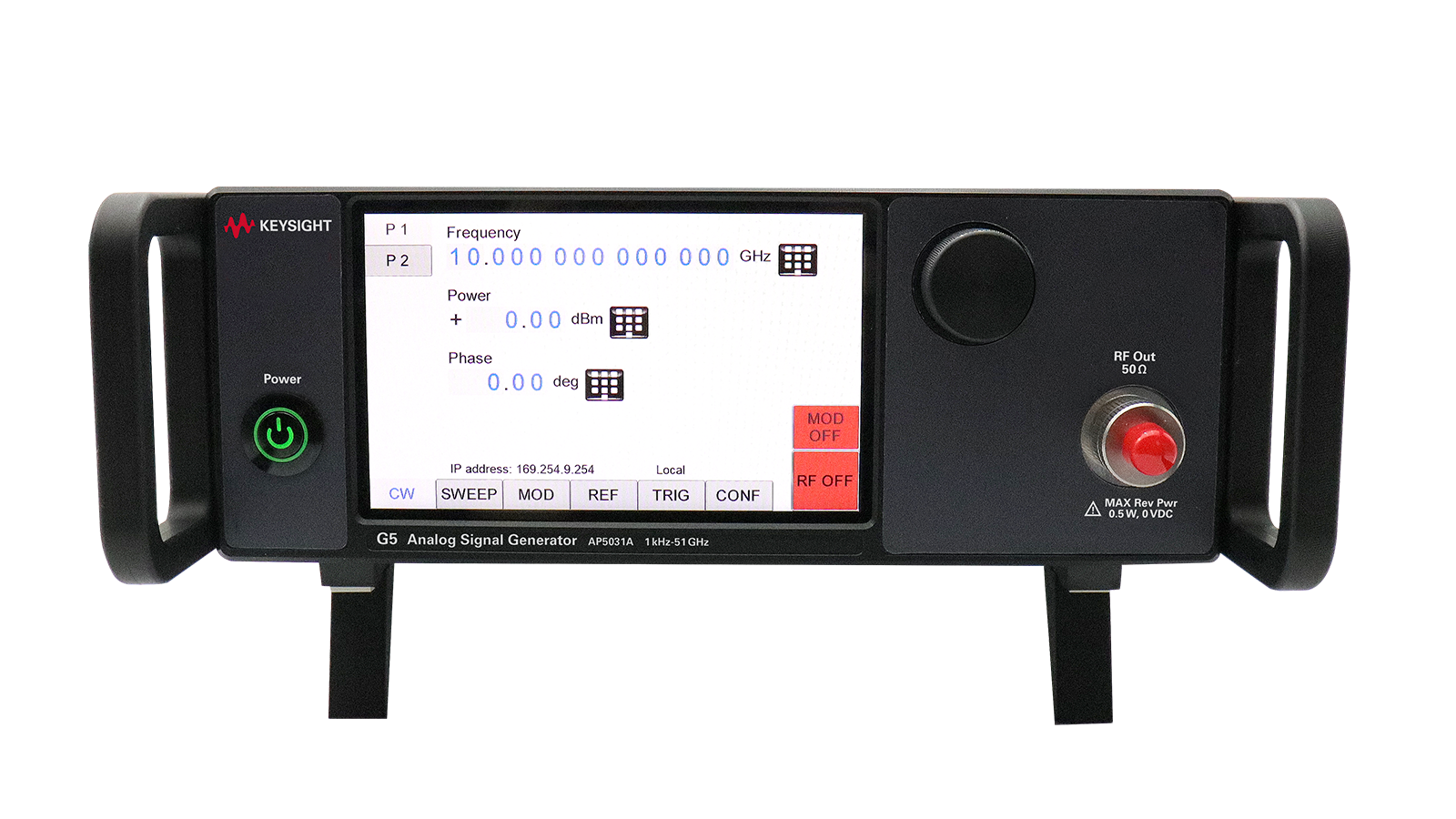
Amplifier Gain Solution
See Block Diagram of Amplifier Gain Solution

Explore Products in Our Amplifier Gain Solution
-


![]()
AP5032A Analog Signal Generator, 1 kHz to 51 GHz
-
![]()
AP5031A Analog Signal Generator, 1 kHz to 90 GHz


Discover Resources and Insights
Additional resources for Measuring Amplifier Gain Compression and P1dB
Related Use Cases

-
![]()
Learn More
How to Perform IoT RF Receiver Testing
Validate IoT receiver sensitivity and robustness with controlled RF signals from the N5166B.
Learn More

-
![]()
Learn More
How to Create Custom I/Q Waveforms
Create and download custom baseband I/Q waveforms with the N5166B for flexible RF signal generation and receiver test.
Learn More
-
![]()
Learn More
How to Generate Interference Signals for Receiver Testing
Use the Keysight N5166B Essential Vector Signal Generator to generate controlled RF interference signals for receiver robustness and coexistence testing.
Learn More

Get in Touch with One of Our Experts
Need help finding the right solution for you?