What are you looking for?
Signal Generators and Signal Sources
Push your device and system within and beyond its limits
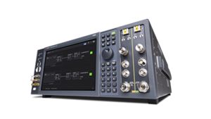

Accelerate Millimeter-Wave Testing
Simplify and accelerate testing of millimeter-wave products for 5G, defense, radar, and non-terrestrial networks with the VXG signal generator that offers wide bandwidth, a maximum frequency of up to 110 GHz, and automated test software with pre-configured waveforms. This solution minimizes the challenges of over-the-air testing while delivering ultra-low phase noise and high output power. It ensures accurate, repeatable results, providing faster validation and greater confidence in your device's performance across evolving standards.
Find the Signal Source That's Right For You
Keysight offers the widest selection of signal sources from baseband to 110 GHz, with frequency extensions to 1.1 THz. Our signal generators are widely used and trusted for 5G, satellite, aerospace, and advanced wireless communications testing. Each delivers outstanding performance in signal purity and reliability.
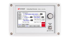


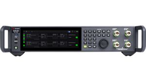
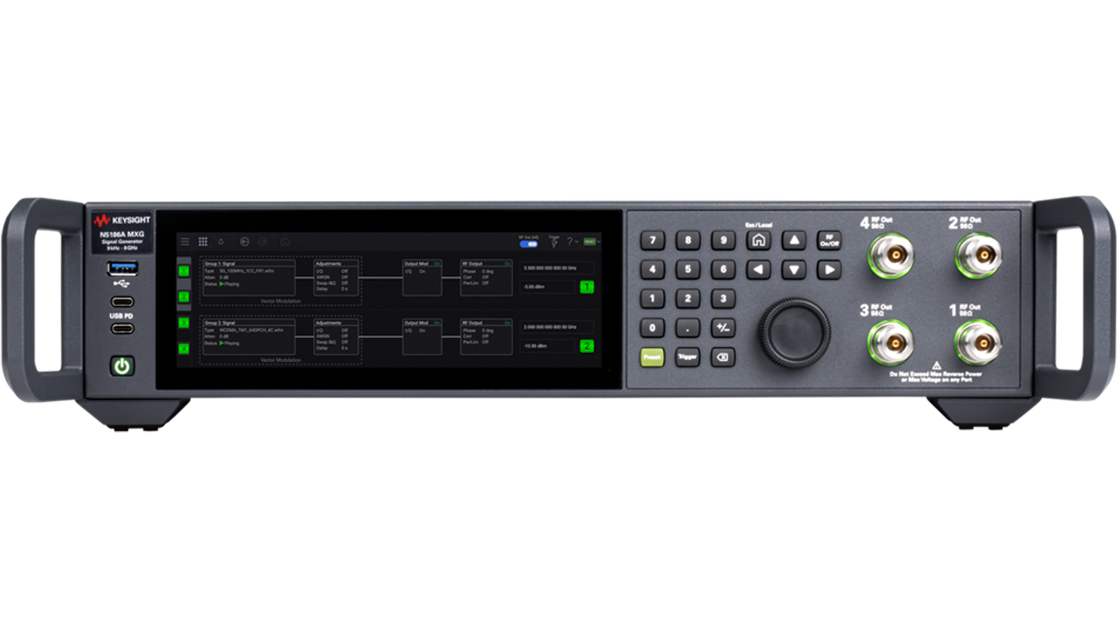

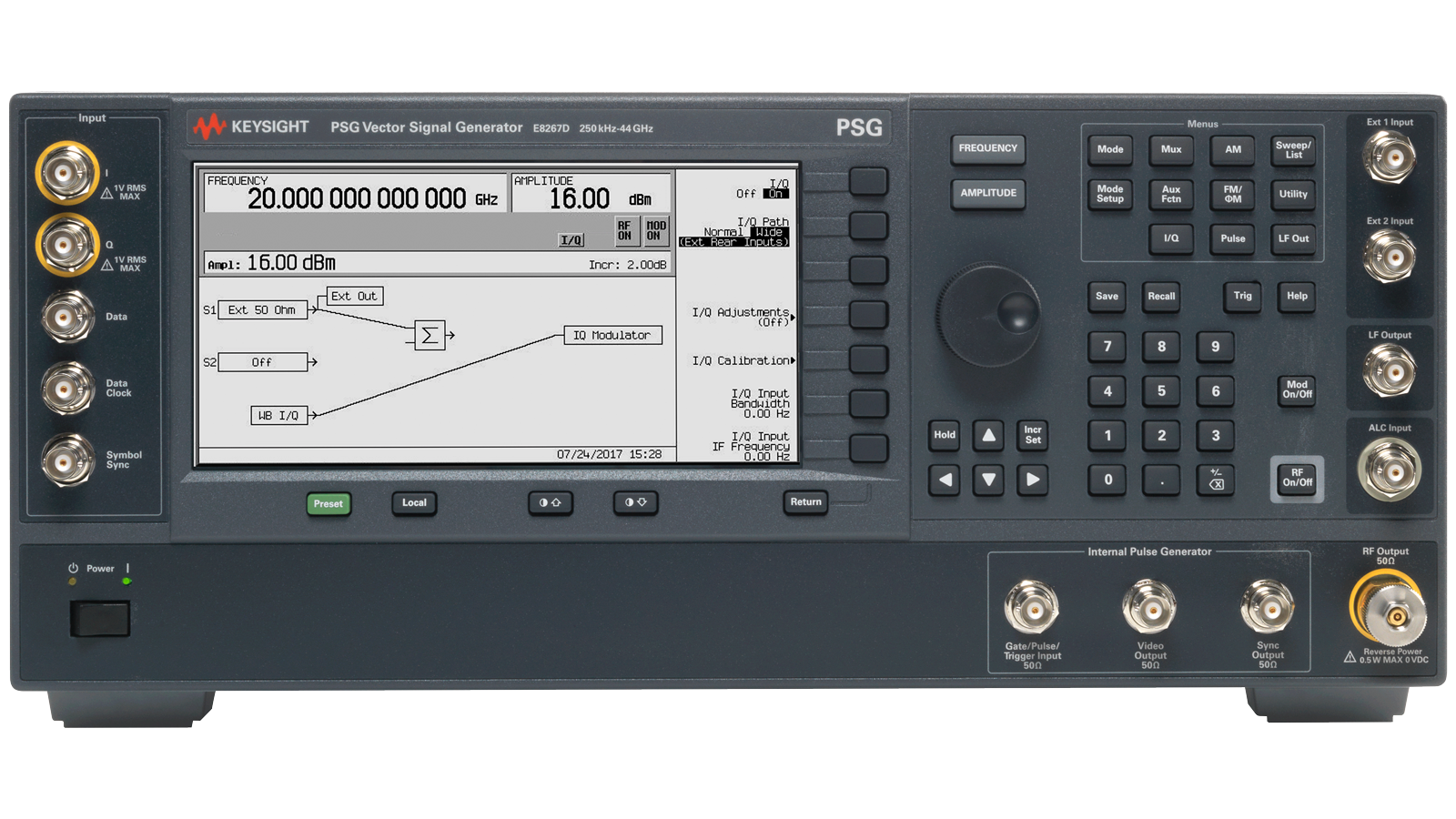
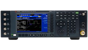

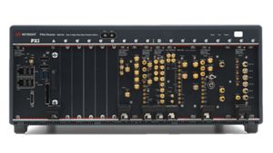


PathWave Signal Generator Software
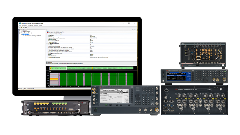
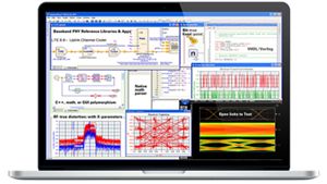
PathWave Signal Generator software is a flexible suite of signal-creation tools that accelerates design and testing by reducing time spent on signal simulation. Its performance-optimized reference signals, validated by Keysight, enhance the characterization and verification of your devices.
- Create performance-optimized reference signals
- Validate component, transmitter, and receiver testing
- Ensure designs meet the latest standards
- Speed signal creation and reduce simulation time
Eliminate Uncertainties from Your Test Results with a Reliable Signal Source
In the race to get to market faster, you need test results you can trust. Selecting the right, reliable testing instrument for the job can make a difference.
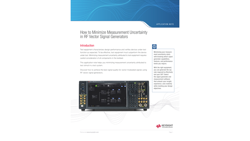
Keysight test experts describe the fundamentals of signal generators in the white papers below. They will help you choose the right RF signal source with confidence for your next design or test project.
Related Use Cases


How to Create Electronic Warfare Test Signals

How to Test Automotive SerDes Receiver Conformance
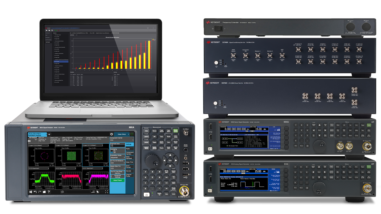
How to Test IoT Regulatory Compliance
How to Simulate EW Threat Scenarios

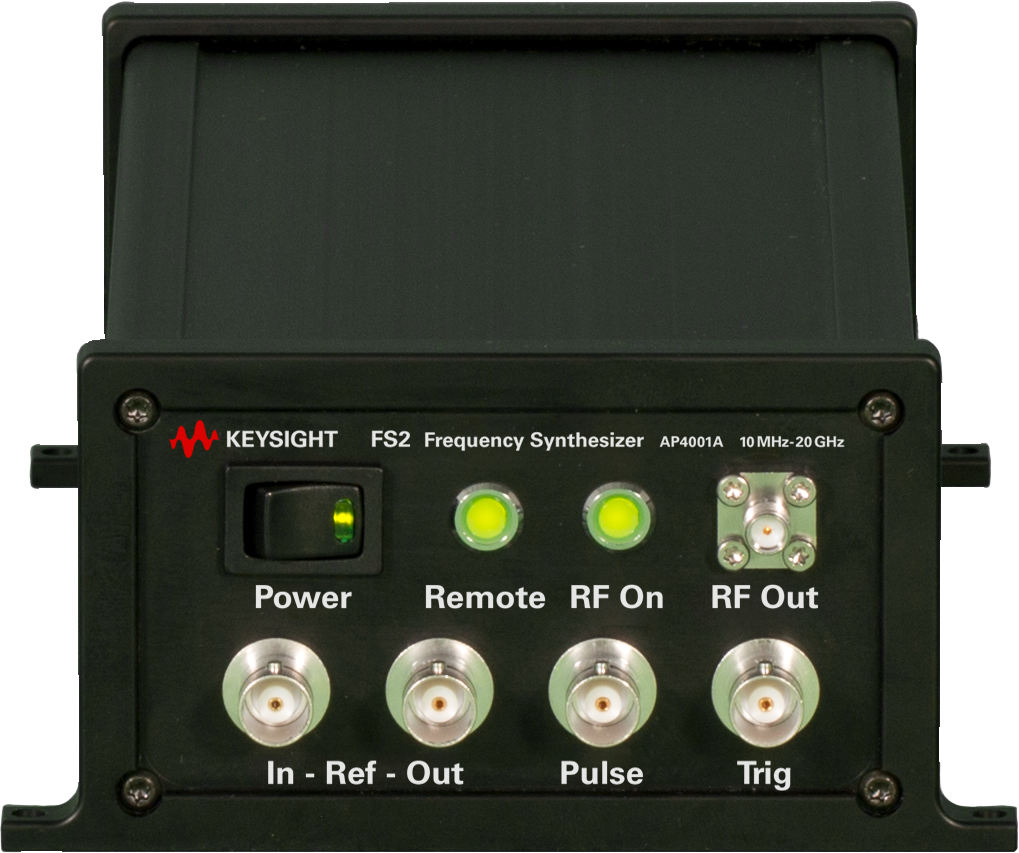
How to Maintain Phase Alignment Across RF Outputs

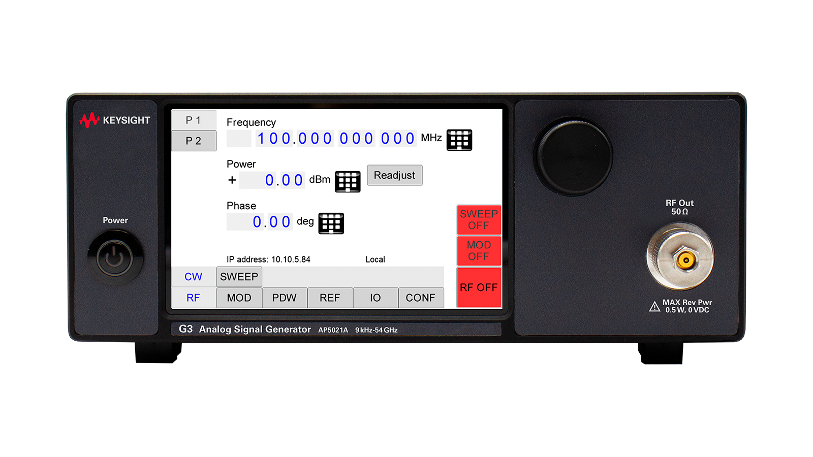
How to Program Multi-Channel RF Signal Generators
Extend Your Signal Generator Capabilities With The Right Tools
Get more functionality out of your test instrument today by pairing it with the right accessories to improve productivity and the right Keysight PathWave design and test automation software to accelerate your product development.





Featured Resources for Signal Generators and Signal Sources









Signal Generator FAQs
An RF signal generator is an electronic device that generates repeating or non-repeating waveforms to test and evaluate electronic test equipment. It serves as a versatile instrument in electronic engineering, producing signals that simulate real-world conditions to verify the performance of circuits, systems, and components. These devices are essential for applications ranging from basic audio testing to advanced RF and microwave communications, allowing engineers to apply controlled signals and impairments to assess how products behave under various scenarios. Historically, signal generators have evolved from simple audio oscillators, like those used in calibrating sound systems for films in the 1940s, to sophisticated tools capable of generating complex modulated signals for modern technologies such as 5G.
The fundamental operation of a signal generator involves key components such as an oscillator, modulator, amplifier, and output stage. The process starts with the oscillator creating a stable waveform, which is then shaped and modulated to produce the desired signal type, including variations in amplitude, frequency, or phase. This enables the generation of diverse waveforms like sine, square, triangle, sawtooth, or arbitrary patterns, each tailored for specific testing needs. Advanced models incorporate modulation techniques such as I/Q modulation, amplitude modulation (AM), frequency modulation (FM), or phase modulation (PM) to convey information and mimic real-world signal behaviors.
Key specifications of signal generators include frequency range, modulation bandwidth, output power, spectral purity, and modulation capabilities—all of which define their suitability for different applications. The frequency range of a signal generator is the span of carrier frequencies that the generator can produce at its output. Modulation bandwidth is the maximum frequency range over which a signal generator or communication system can apply modulation to a carrier signal while maintaining specified performance. Spectral purity encompasses phase noise, harmonics, and spurious signals to ensure clean outputs. For digital communications, metrics such as error vector magnitude (EVM) and adjacent channel power ratio (ACPR) are essential for assessing distortion and overall signal fidelity. Additional parameters like sampling rate, phase-lock modes, and output impedance enhance versatility and help prevent issues such as power loss or signal degradation.
In practical applications, signal generators are used for troubleshooting circuits by injecting known signals, simulating sensor data for system validation, and characterizing components like filters through frequency sweeps. They play a vital role in industries such as telecommunications, aerospace, automotive, and audio engineering, enabling tests for RF amplifiers, transceivers, medical devices, and more. Overall, the accuracy of a signal generator, encompassing amplitude, frequency, and spectral aspects, is paramount, as inaccuracies can mask the true performance of the device under test, leading to unreliable results in product development and verification.
Learn about signal generator specifications in our blog, Learn the Basics of Signal Generator Accuracy
Max frequency: The maximum frequency of a signal generator is critical because it indicates the highest frequency it can produce. This aspect is essential for ensuring compatibility with target applications. For instance, in wireless communications, radar, and 6G research, the signal generator must encompass the necessary frequency bands to accurately test and validate devices by simulating real-world conditions.
Modulation Bandwidth: Modulation bandwidth refers to the frequency range over which a signal can be effectively modulated to carry information in a communication system. Wider bandwidths are essential for testing modern communication systems, radar, and 6G applications, which require high data rates, complex modulation schemes, and wideband signals such as 5G NR, Wi-Fi 7, and ultra-wideband (UWB).
Number of channels: Multi-channel signal generators are essential for applications such as MIMO (multiple-input, multiple-output) testing, beamforming, radar simulations, and phase-coherent signal generation. Precise synchronization between channels is critical for accurate device characterization and system performance evaluation. For applications such as beamforming, the signal must be phase-coherent and time-aligned.
Phase noise: Phase noise refers to the short-term, unwanted fluctuations in a signal’s phase, manifesting as jitter in the time domain and sideband noise in the frequency domain around the carrier signal. It is a crucial parameter in RF and microwave applications because high levels of phase noise can degrade signal integrity, modulation accuracy, and overall system performance in applications such as communication systems, radar, or any application requiring precise timing or synchronization.
Output power: The output power of an RF signal generator refers to the amount of RF energy delivered by an output port, measured in dBm (decibels relative to 1 milliwatt) or watts (W). It represents the strength of the RF signal that the generator produces. Key benefits of high output power include:
- Overcomes losses in test setups from cables, connectors, and attenuators.
- Extends the dynamic range of testing, where both weak and strong signals need to be accurately characterized.
- Improves the Signal-to-Noise Ratio by reducing noise influence and making measurements more precise. This assumes a constant noise floor.
- Tests high-power DUTs (Devices Under Test), including power amplifiers, antennas, and transmitters that require higher input power to function properly.
RF signal generators have a broad range of applications across various industries, utilizing their capability to generate controlled radio frequency signals for testing, development, and operational purposes. Here are some key applications:
1. Telecommunications testing: RF signal generators simulate signals to test communication equipment such as mobile phones, base stations, and satellite systems. They help evaluate receiver sensitivity, signal quality, and performance under various modulation schemes (e.g., 4G, 5G, Wi-Fi).
2. Electronics development and calibration: Engineers utilize RF signal generators to design and troubleshoot RF circuits, including amplifiers, mixers, and filters.
3. Wireless system validation: In the development of wireless technologies (e.g., Bluetooth, Zigbee, IoT devices), signal generators produce complex modulated signals to assess system performance, interoperability, and compliance with industry standards.
4. Aerospace and defense: RF signal generators simulate radar signals, electronic warfare scenarios, and communication links for testing radar systems, missile guidance, and military radios. They can introduce noise or interference to evaluate system robustness.
5. Automotive industry: With the rise of connected vehicles, automotive radar (e.g., for adaptive cruise control) and vehicle-to-vehicle communication systems are tested with precise RF signals produced by signal generators.
In essence, RF signal generators are indispensable tools for simulating real-world RF environments. They enable the design, testing, and optimization of systems that rely on radio frequency technology across diverse sectors.
The difference between a vector signal generator and an analog signal generator lies in their capabilities and the types of signals they produce, catering to distinct testing and application needs in RF engineering.
An analog signal generator produces continuous RF signals with basic parameters, including frequency, amplitude, and phase modulation. It generates sine waves or other straightforward waveforms. While analog signal generators are typically simpler to operate, they cannot replicate the advanced digital modulation techniques utilized in modern communication systems.
In contrast, a vector signal generator can generate complex, digitally modulated RF signals mimicking real-world communication signals, such as those used in wireless standards like LTE, Wi-Fi, or 5G. Vector signal generators control both the amplitude and phase of the signal, producing intricate waveforms with specific modulation types (e.g., QAM, PSK, OFDM) and can introduce impairments like noise or fading for realistic testing. This makes them essential for designing, testing, and troubleshooting modern digital communication systems.
There are various types of signal generators:
- Analog Signal Generator
- Vector Signal Generator
- Arbitrary Waveform Generator
- Radio Frequency (RF) Signal Generator
- Function Generator
- Pulse Generator
- Digital Pattern Generator
Spectral purity represents a signal’s inherent stability, particularly in terms of frequency consistency, and encompasses both short-term and long-term stabilities. Spectral purity refers to the extent to which a signal is free from unwanted frequencies or noise.
Long-term stability, or drift, is measured over periods longer than one second. The rate at which a signal drifts off frequency can occur over minutes, hours, days, or even months. Modern signal generators are designed to offer proven long-term stability.
The primary concern is short-term stability, specifically frequency changes that occur in less than one second. These fluctuations come from non-deterministic signals like noise, shot noise, and 1/f flicker noise that modulates the carrier.
The components of spectral purity include:
Single-Sideband Phase Noise
There are many ways to define spectral purity. Figure 1 illustrates the most common and meaningful method to specify short-term stability by plotting the signal generator’s single-sideband (SSB) phase noise in a 1 Hz bandwidth versus the offset from the carrier. This example expresses the SSB phase noise in dB relative to the carrier (dBc). A 1 Hz bandwidth facilitates easy calculation and noise comparison in other bandwidths. This plot is a graphical representation of the phase noise distribution on one side of the carrier.
Spurious
Mixing and dividing signals to get the carrier frequency creates non-random or deterministic signals. Signals are harmonically related to the carrier and are subharmonics. The amplitude of the non-harmonic spectral line, known as spurious, is relative to the carrier (dBc).
Residual Frequency Modulation
Residual frequency modulation (FM) refers to the unwanted angular modulation or FM inherent in a signal generator when all the modulation is deactivated. This result includes spurious and phase noise effects, as shown in Figure 1. The integral or area under the single-sideband (SSB) curve, with limits set by the post-detection bandwidth, defines this modulation. Common bandwidths are 300 Hz to 3 kHz and 20 Hz to 15 kHz.


Figure 1. Signal generator SSB phase noise and spurious effects on one side of the carrier
Two signals are coherent if they have a constant relative phase at all times. Figure 2a illustrates two non-coherent signals with phase variances, and 2b shows coherent signals with fixed phase offset. When present together, signals will combine constructively or destructively, depending on their relative phase.
In cases where you characterize a multichannel component such as a phased-array antenna, you need to precisely control the phase angle relationship between the channels (Figure 2c). For digitally modulated signals, phase coherence indicates both timing synchronization between baseband generators and phase coherence between RF carriers (see Figure 2d). Similarly, radar pulses require precise timing of the pulse bursts to simulate the appropriate spatial delays (see Figure 2e).

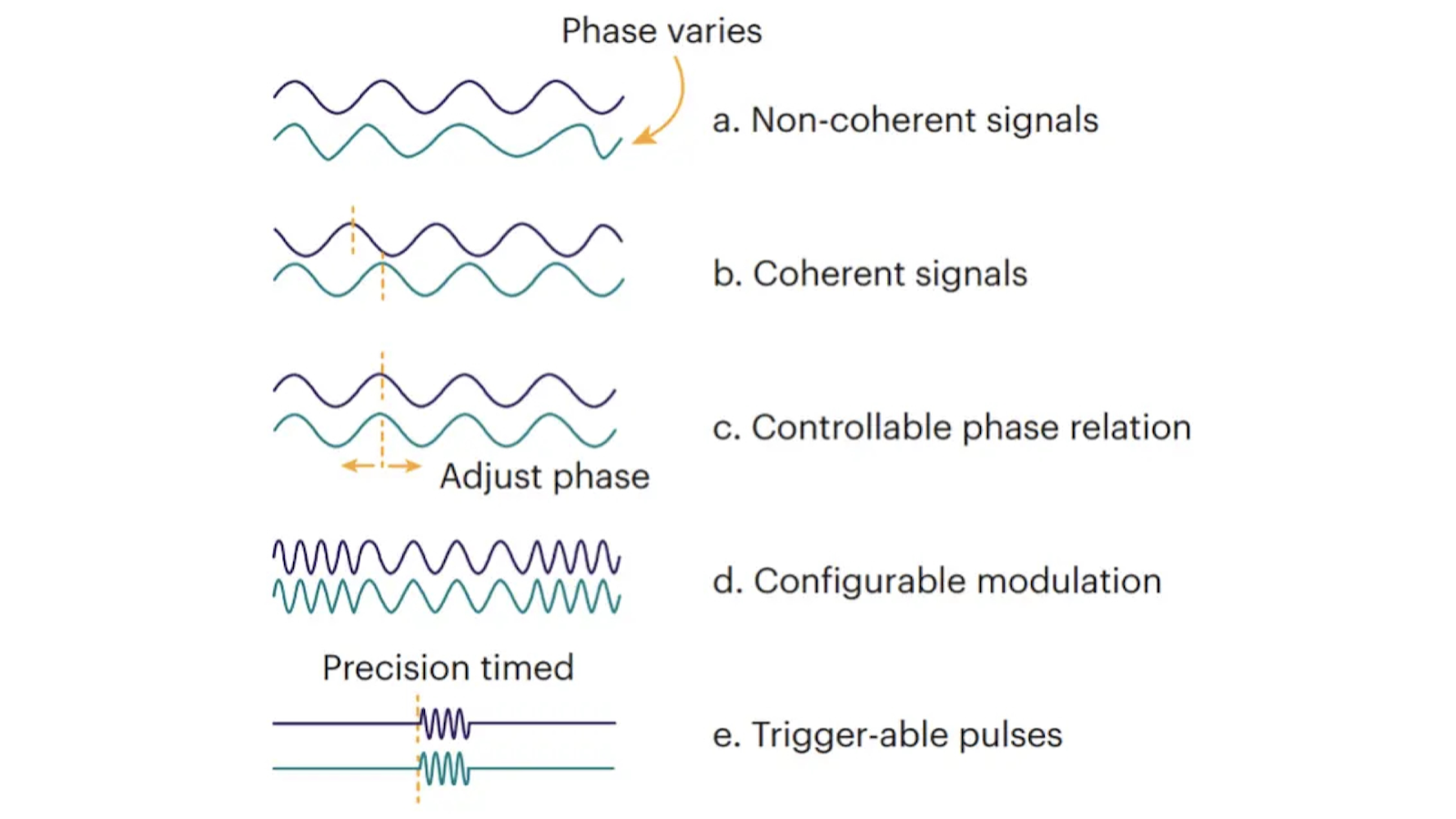
Figure 2. Phase relations between two signals


Want help or have questions?