Testen von Schaltnetzteilen

Charakterisierung von Schaltnetzteilen mit einem Oszilloskop
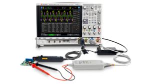
Die Charakterisierung des Betriebs von Schaltnetzteilen erfordert eine breite Palette von Messungen mit einem Oszilloskop. Sie müssen den Eingang, das Schalten und den Ausgang des Netzteils analysieren. Außerdem müssen Sie Frequenzgangmessungen durchführen, wie z. B. das Stromversorgungsunterdrückungsverhältnis (PSRR) und das Regelkreisverhalten. Diese Messungen werden in der Regel mit einem Vektor-Netzwerkanalysator (VNA) durchgeführt.
Führen Sie diese Messungen mit einem Oszilloskop mit Leistungsmesssoftware, einer Schräglagenfixierung, einer Hochspannungs-Differenzialsonde, einer Stromsonde und einer passiven Spannungssonde durch. Die Schräglagenfixierung gleicht den Unterschied in der Ausbreitungsverzögerung zwischen den Messfühlern aus, um genauere Messungen zu ermöglichen. Deskewing ist entscheidend für die Messung der Schaltverluste. Die Zeitverzögerung kann zu erheblichen Unterschieden bei den Leistungs- und Energiemessungen während der Ein- und Ausschaltphasen der Transistorschaltung führen.

Lösung zur Charakterisierung von Schaltnetzteilen
Siehe Demo zur Charakterisierung von Schaltnetzteilen
Entdecken Sie Produkte für unsere Lösung zur Charakterisierung von Schaltnetzteilen
-

![]()
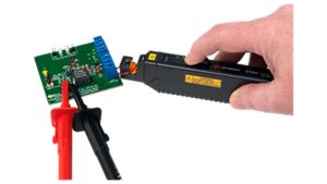
N7026A Hochempfindlicher AC/DC-Stromzangenfühler
-
![]()
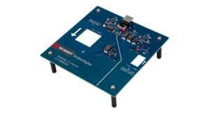
U1880A Leistungsmessungs-Schräglagenhalterung
-

![]()
D4000BDLB Ultimatives Software-Paket für die 4000 X-Serie
-
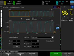
![]()
DSOX4WAVEGEN2 WaveGen, integrierter Zweikanal- und Arbiträrwellenformgenerator für Oszilloskope der 4000 X-Serie
-
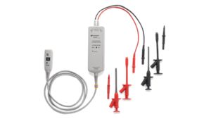
![]()
N2790A Hochspannungs-Differenzialtastkopf, 100 MHz


Ressourcen und Einblicke entdecken
Zusätzliche Ressourcen für die Charakterisierung von Schaltnetzteilentwürfen
Verwandte Anwendungsfälle

-
![]()
Mehr erfahren
Genaue Messung von tieffrequentem Lärm
Die Erstellung präziser MOSFET-Modelle für niederfrequentes Rauschen (LFN) erfordert die Messung des ultra-niederfrequenten Rauschens sowohl auf Gehäuse- als auch auf Wafer-Ebene. Erfahren Sie, wie Sie zuverlässige LFN-Messungen durchführen, um robuste MOSFET-Niederfrequenzrauschmodelle zu entwickeln.
Mehr erfahren

-
![]()
Mehr erfahren
Entwurf von sanft schaltenden Leistungsumrichtern
Die Entwicklung eines effizienten Stromrichters bei hohen Frequenzen erfordert den Einsatz von Soft-Switching-Techniken im gesamten Betriebsbereich, um die Schaltverluste zu minimieren. Erfahren Sie, wie Sie komplexe Steuerungsparameter simulieren können, um ein robustes Design für sanft schaltende Stromrichter zu ermöglichen.
Mehr erfahren
-
![]()
Mehr erfahren
Durchführung von PCBA-Chipsatztests
Die Prüfung von Leiterplatten erfordert einen Boundary-Scan-Test. Erfahren Sie, wie Sie PCBA-Chipsätze mit einem In-Circuit-Tester und einem Boundary-Scan-Analysator testen können.
Mehr erfahren

Nehmen Sie Kontakt mit einem unserer Experten auf
Benötigen Sie Hilfe bei der Suche nach der richtigen Lösung für Sie?