How to Measure Passive Component Impedance

Measure Passive Components Across Test Frequencies
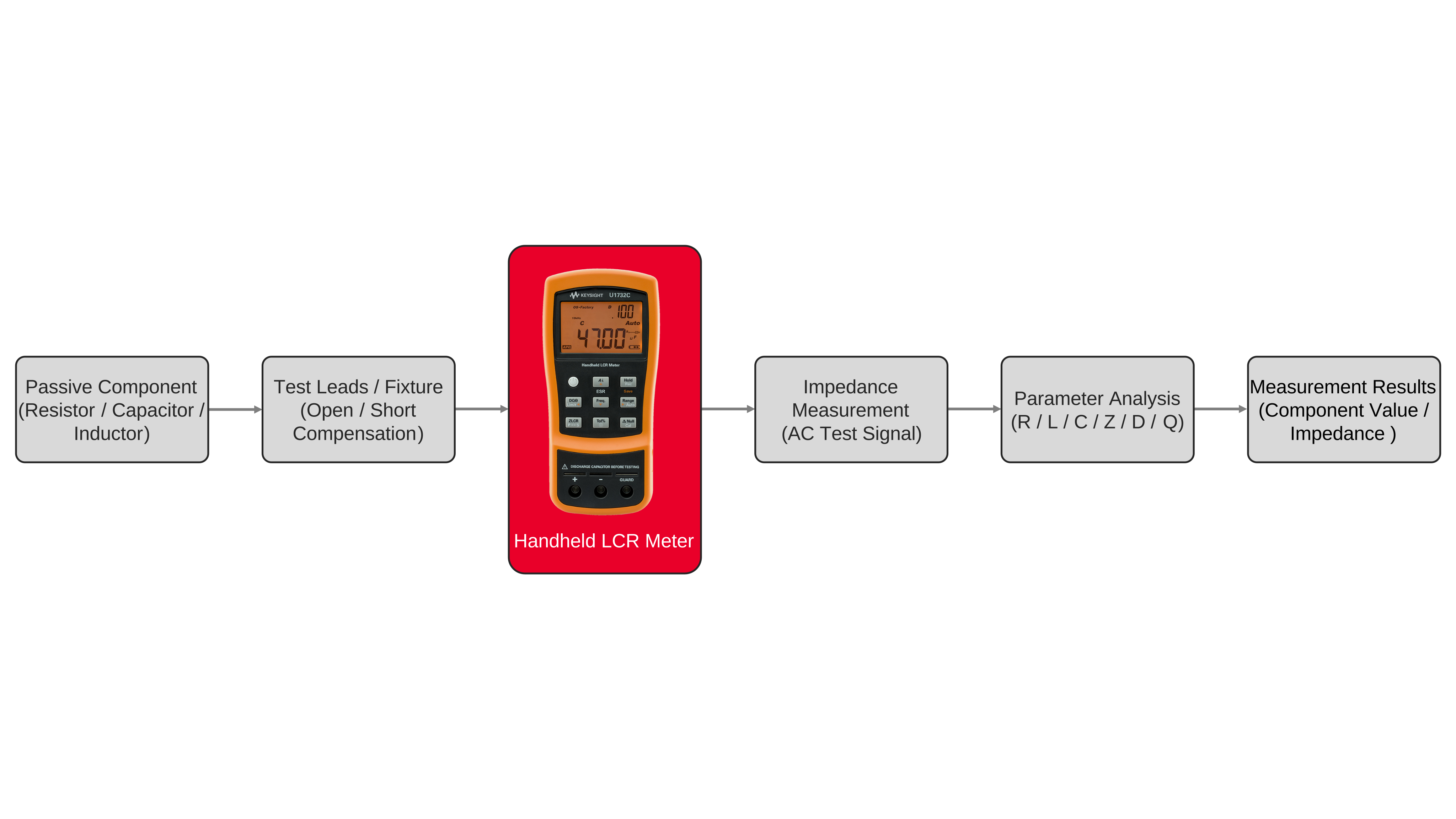
Passive-component measurement characterizes resistance, capacitance, and inductance as frequency-dependent impedance quantities rather than treating components as ideal elements with a single fixed value. The test requires an inductance, capacitance, and resistance (LCR) meter, suitable test leads or a component fixture, and a device under test connected with short, repeatable electrical paths. Before measurement, select the appropriate test frequency, measurement function, and equivalent-circuit representation for the expected impedance of the component. An LCR meter applies an alternating-current test signal to the device and evaluates the resulting voltage and current relationship to determine electrical impedance. Impedance contains a real component, associated primarily with resistance, and an imaginary component, associated with capacitive or inductive reactance. From these measured quantities, the instrument calculates parameters such as resistance, capacitance, inductance, impedance magnitude, phase angle, equivalent series resistance, dissipation factor, and quality factor. For resistance measurement, the primary result represents the resistive portion of the component while secondary parameters can reveal reactive behavior that becomes more significant at higher frequencies. For capacitance measurement, the instrument evaluates capacitive reactance and converts the measured impedance into an equivalent capacitance value using the selected test frequency and circuit model. For inductance measurement, the same process uses inductive reactance to calculate an equivalent inductance value. Performing impedance measurement at multiple frequencies provides a structured way to observe how each component behaves as reactance changes. A resistor may remain relatively constant across the measurement range, while capacitive reactance generally decreases and inductive reactance generally increases as frequency rises. Measuring these changes alongside phase and secondary parameters provides a consistent method for comparing actual component behavior with the expected series or parallel equivalent-circuit response.
The measurement setup should also account for electrical contributions introduced by the connection between the LCR meter and the device under test. Test leads, cables, adapters, fixtures, contact resistance, stray capacitance, and residual inductance can become part of the measured impedance unless their effects are minimized or compensated. Connections should remain short, mechanically stable, and consistent between measurements, and the selected fixture should match the component package and expected impedance range. Where the measurement system provides open, short, or other compensation functions, perform the applicable correction with the fixture configured in the same arrangement that will be used for the component. Open compensation can reduce the influence of stray admittance such as fixture capacitance, while short compensation can reduce residual series impedance associated with leads, contacts, and fixture conductors. After compensation, connect the component without changing the fixture geometry, select the required frequency and measurement parameters, and record the primary resistance, capacitance, or inductance result together with the secondary quantities needed for evaluation. When measurements are repeated across frequency, changes in impedance magnitude, phase angle, dissipation factor, quality factor, or equivalent series resistance can be compared with the expected equivalent-circuit behavior. Real capacitors can exhibit series resistance and parasitic inductance, while real inductors can include winding resistance and parasitic capacitance, so measured values may depart from the nominal component value as frequency changes. A complete LCR meter workflow therefore combines resistance measurement, capacitance measurement, inductance measurement, and impedance measurement under controlled test conditions. Keeping the measurement frequency, fixture configuration, compensation state, connection method, and equivalent-circuit selection consistently allows results to be compared across individual components, component values, production samples, or repeated bench measurements while preserving the electrical conditions under which each measurement was obtained.


Passive Component Impedance Measurement Solution
Block Diagram of Passive Component Impedance Measurement Solution

Explore Products in Our Passive Component Impedance Measurement Solution
-

![]()
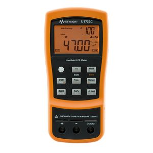
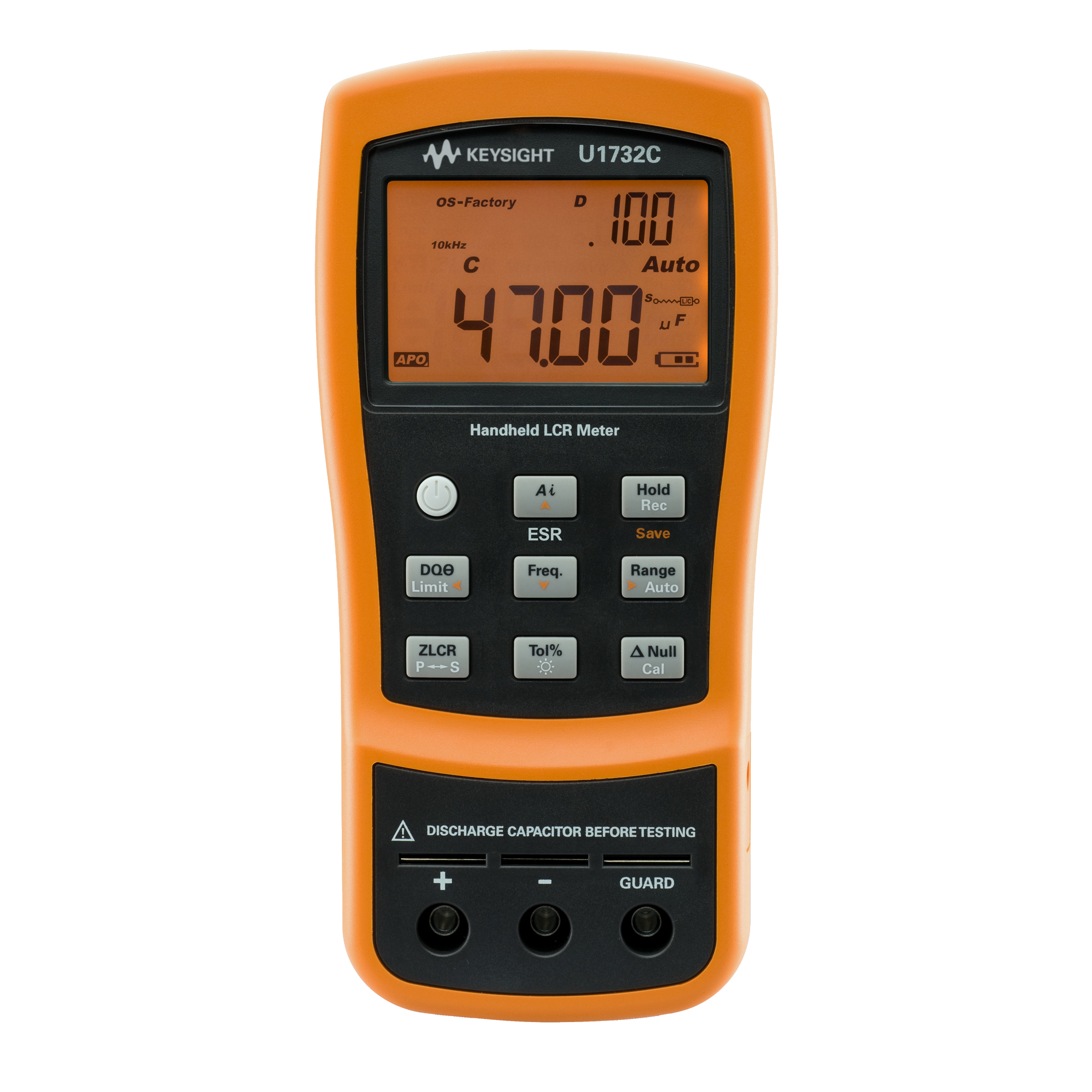
U1732C 100Hz / 120Hz / 1kHz / 10kHz Handheld LCR Meter

Discover Resources and Insights
Additional Resources for Passive Component Impedance Measurement
Related Use Cases


-
![]()
Learn More
How to Evaluate Capacitor Stability at Multiple Frequencies
Evaluate capacitor stability at multiple test frequencies using high-speed capacitance and dissipation factor measurements with a capacitance meter.
Learn More

-
![]()
Learn More
How to Measure Material Permittivity and Permeability
Measure permittivity and permeability across frequency to characterize the electrical properties and losses of dielectric and magnetic materials.
Learn More
-
![]()
Learn More
How to Characterize Electronic Components Across Frequency
Characterize electronic components across frequency by measuring impedance, phase, resistance, reactance, capacitance, and inductance.
Learn More

Get in Touch with One of Our Experts
Need help finding the right solution for you?