
M809256PB OIF-CEI CEI-56G PAM4 Pre-Compliance Receiver Test Application
Data Sheets
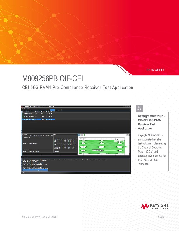
Key Features
- CEI-56G-VSR PAM4 (host and module), CEI-56G-MR and -LR PAM4 from 18 to 29 Gbaud
- Guided setup, automated stress signal calibration and pre-compliance measurement
- HTML test report
- Data Analytics Enabled
- Choose between node-locked, transportable, network, USB-dongle license types either perpetual or subscription with 6/12/24/36-month duration
Description
The M809256PB receiver test application is designed to assist and simplify the stress signal calibration used for testing the inputs of CEI-56G-VSR/-MR/-LR PAM4 electrical interfaces using a Keysight M8040A 64Gbaud Higher Performance BERT and a Keysight Digital Communication Analyzer (DCA) Oscilloscope. It reduces user interaction to a minimum and performs all required calibration routines and compliance testing automatically by remote controlling all required instruments. A wide range of hardware configuration is supported, thus protecting your investment.
Calibrations and Tests Covered by M809256PB Pre-Compliance Receiver Test
Application CEI-56G-VSR (host or module)
OIF CEI-56G-VSR PAM4 defines the stress signal through a mated host compliance board (HCB) and
module compliance board (MCB) connection. Both the receiver side as well as the transmitter side have
equalization capabilities. The definition of the stress signal assumes an optimized link. Therefore, the
transmitter of the receiver test equipment as well as the receiver of the signal measurement device must
be optimized for the given stress channel. This must be done iteratively for each test setup. The
standard requires the transmitter equalization (TxEQ) to be kept as small as possible to increase the
stress on the device under test’s receiver (DUT RX). If performed manually, this procedure is very time
consuming. However, the M809256PB Receiver test application performs this task automatically.
Example setup for VSR Host input stress eye calibration
- MCB and HCB
- X-Talk Generator Data Out 2 P/N to TPI P/N of MCB
- Termination via 50 Ohm to TPIaP/N of HCB
- Victim Generator Data Out 1 P/N to TP4aP/N of HCB
- Oscilloscope CVH1/CH2 to TP4 P/N of MCB
All calibration steps are automated. The test application prompts the user whenever user interaction is
required for connecting or modifying the test setup. Detailed connection diagrams and instructions are
provided by the test application.
• OIF CEI-56G-VSR host and module
· Calibrations are implemented according to OIF-CEI-4.0 Common Electrical I/O (CEI) -
Electrical and Jitter Interoperability Agreements, December 29, 2017
- Crosstalk amplitude and transition time
- Victim lane amplitude
- Victim lane UUGJ
- Victim lane SJ
- Stressed eye
· Test is implemented according to IEEE Standard for Ethernet, Annex 120E
- Stressed input
- Voltage tolerance
OIF CEI-56G-MR/-LR PAM4
Both 56G-LR and -MR test procedures rely on the Channel Operating Margin (COM) method1. COM has been first introduced to measure the performance margin of a channel and then extended to digital systems. Interoperability of digital receiver can be expressed in terms of COM requirements. COM is calculated out of channel 4-ports S-parameters (for victim and aggressor lanes) as well as the noise and equalization functionality of the considered transmitter and receiver. The resulting COM metric is the ratio of the signal amplitude (after equalization) to the noise and cross-talk peak-to-peak amplitude measure during a time interval depending on the target BER.
Setup for MR Receiver Interference and Jitter Tolerance Test
- Set Device to Loopback.
- Victim Generator Data Out 1 P/N to test point T P/N of ISI channel.
- ISI channel test point T P/N to thru path of matched directional coupler pair.
- Noise Generator Data Out 1 P/N to couple path of matched directional coupler pair.
- Directional coupler Data Out P/N to Test point T P/N of Receiver test fixture.
- Receiver test fixture Test point T P/N to Receiver under test.
- Victim Analyzer Data In P/N to Test point of looped back signal P/N via Pick-Off.
- Recovered Clock Out from Clock Recovery to Victim Analyzer Clk In.
- Unused ports with 50 ohms.