Over-the-Air Automotive Radar Test Calibration
Demos
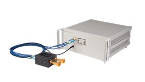
Setting up over-the-air (OTA) test environments for automotive radar modules have their challenges. If this was for a production line with multiple system setups, this would be a tedious process. One example, measurement of radar transmit power, how do we maintain consistency in the measured results? The setup will consist of certain deficiencies to introduce possible errors, like the horn antenna gain flatness, co-polarization angle between radar and horn antenna, or potential mismatch in the conductive path. How to account for all these deficiencies or pathloss errors that could impact the measured results? This video example makes use of an over-the-air (OTA) setup with a radar target simulator (RTS0, simulating targets for a radar module under test. Distance 1 meter separates the radar target simulator and the radar module. The radar target simulator is equipped with a secondary IF (IF2) receive channel for measurement of transmit power from radar module. RTS receiver (RTS Rx) attached to wave guide and horn antenna, potential mismatches and errors. Keysight U9361M receiver calibrator (RCal) is a compact palm sized device, provides clean calibrated millimeter wave source up to 110 GHz. Securing RCal with a standardized gain horn antenna (SGH) at the position of the radar module, we now have a known calibrated transmit (Tx) source. Measuring known Tx source using IF2, we can easily calculate entire pathloss up to IF2 channel, which includes free space loss OTA path together with horn antenna and waveguide connections. In this example, E8719A RTS is installed with an automated calibration feature that. When connected with U9361M RCal and Keysight spectrum analyzer connected to RTS IF2, this feature will automatically run through sequence of steps, for calculating the path loss. Additional value of this feature, the pathloss data is stored into the RTS. This data can be used to improve simulated parameters like radar cross section (RCS).