Resource Guide
How to Master EMF Testing: A Practical Guide for Electrical Engineers


Introduction
Imagine you’re deep into a product validation cycle. The design looks solid on paper, but when you start testing, unexpected electromagnetic emissions appear. The results are inconsistent, the readings drift, and suddenly compliance with IEC and FCC standards feels just out of reach.
It’s a familiar situation for many engineers. The pressure to deliver safe, reliable products while wrestling with the complexity of EMF testing in real-world environments.
Reliable measurements aren’t easy to achieve. Evolving standards, crowded signal environments, and the sheer precision required can make EMF testing feel like chasing a moving target. Without the right approach, it’s easy to waste time troubleshooting noise sources or repeating tests that never seem to line up.
But mastering EMF testing pays off in ways that go far beyond passing an audit. When you have a consistent, accurate workflow, you validate designs faster, reduce costly interference problems, and build products that perform safely in the field.
In this guide, you’ll see why EMF testing matters, which instruments you need, and how to perform common test procedures step by step. You’ll also learn how to troubleshoot issues, apply advanced tips, and understand the real-world impact of strong EMF practices.
What EMF/EMC Testing Is—and What It’s Used For
Electromagnetic field (EMF) testing is the process of measuring electric and magnetic fields generated by a device, system, or installation. For electrical engineers, this means quantifying the strength, frequency, and behavior of fields that can affect performance, reliability, and safety.
Closely tied to EMF is electromagnetic compatibility (EMC), which focuses on ensuring that a product functions properly in its intended environment without creating interference for other devices. In short, EMF testing tells you what’s present, while EMC testing ensures your design can coexist without conflict.
The role of EMF testing extends throughout the product lifecycle. Early in design, it helps identify potential problem areas like poor shielding or grounding. During validation, it verifies compliance with regulatory standards such as IEC and FCC, which dictate exposure limits and emission thresholds. And once a product is in the field, EMF testing continues to support safety checks, quality assurance, and performance optimization.
A common misconception is that EMF testing can “guarantee” immunity to all interference. In reality, it provides a structured, repeatable way to measure and minimize risk. Engineers still need to combine these measurements with good design practices to achieve reliable outcomes.
Because of this, EMF testing isn’t an isolated skill. A strong grasp of circuit theory, instrumentation, and signal analysis is essential for interpreting results correctly. Engineers must understand how to take a measurement and how to trace it back to the underlying physics that explain why it’s happening.
The tools you use are just as important as the theory. Oscilloscopes, spectrum analyzers, and calibrated field probes form the backbone of EMF testing setups. Current probes are indispensable for tracing leakage paths and verifying grounding performance, tasks that tie directly into compliance and safety.
If you need a refresher on the fundamentals, see our guide on how to measure current with a multimeter, a skill that underpins ground and leakage tests in EMF workflows.
Essential Instruments for EMF/EMC Testing
Accurate EMF testing depends on having the right instruments. Each plays a specific role in identifying, measuring, and validating electromagnetic behavior, forming the foundation for compliance, safety, and product reliability.
Spectrum Analyzers and Calibrated Field Probes
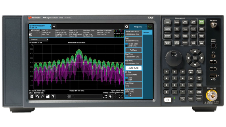
These are the primary tools for conducted and radiated scans. A spectrum analyzer reveals the frequency content of emissions, while calibrated field probes convert surrounding electromagnetic fields into measurable data. Together, they make it possible to detect unwanted signals and quantify them with confidence.
Vector Network Analyzers (VNAs) and Signal Generators
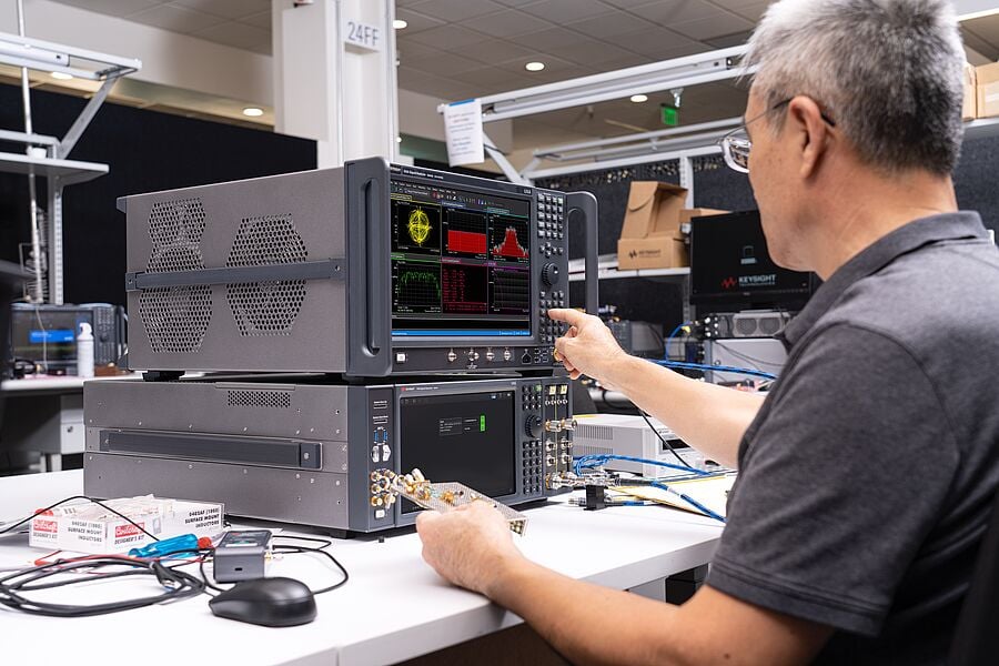
When characterizing filters, cables, and shielding effectiveness, VNAs and signal generators are essential. VNAs measure how signals transmit and reflect through components, while signal generators provide controlled waveforms for testing under specific conditions. This combination helps engineers confirm performance and identify weaknesses in shielding or cabling.
Near-Field E/H Probes and Current Probes
Debugging at the bench requires tools that can get close to the source. Near-field electric and magnetic probes allow you to trace emissions directly to PCB traces or components. Current probes are indispensable for locating unwanted currents in cables and verifying grounding performance, making them key to source localization.
Safety Testers
Electrical safety compliance relies on specialized instruments such as hipot testers, ground bond/continuity testers, and leakage meters. These confirm that insulation, grounding, and protective systems work as intended, preventing dangerous shock or fire risks.
Calibration and Traceability
Even the best instruments are only as reliable as their calibration. Keeping calibration certificates current and clearly affixed provides traceability and ensures measurement validity. For many regulatory audits, updated certificates are the deciding factor between a smooth approval and costly delays.
Step-by-Step EMF Testing Instructions
EMF testing typically follows a series of structured phases, each with its own purpose and measurement focus. Together, these steps verify insulation integrity, grounding safety, leakage control, and electromagnetic emissions. The following overview highlights the main test types, their objectives, and the relative level of effort required.
Test Types vs. Difficulty and Time
| Test type | Objective | Difficulty | Time required |
|---|---|---|---|
| Dielectric strength | Confirm insulation withstands high voltage | Medium | 10–20 min |
| Ground continuity | Verify low-resistance safety ground path | Easy | 5–10 min |
| Leakage current | Measure RF emissions in free space | High | 1–3 hours (precompliance) |
| Conducted emissions | Measure EMI on cables and power lines | High | 1–2 hours (precompliance) |
1. Dielectric Strength Testing
The goal of dielectric strength testing is to determine whether insulation can withstand a specified high voltage without breaking down. This helps confirm that the device under test (DUT) will not pose a shock or fire risk in normal operation.
Setup involves connecting a controlled high-voltage source across the insulation barrier and gradually ramping up the voltage while monitoring leakage current. Probes must be placed according to the DUT’s design and rated insulation paths.
Because this test uses potentially dangerous voltages, strict safety protocols are essential. Always use insulated probes, barriers, and automatic shutoffs to protect both the user and the equipment.
The outcome is usually a simple pass/fail based on whether breakdown occurs. Typical test levels range from hundreds to thousands of volts, depending on device category.
Takeaway: Dielectric strength tests confirm that insulation barriers meet required safety margins before a product enters service.
2. Ground Continuity Testing
This test verifies that the protective ground connection in a device is intact and has low resistance. A reliable ground path ensures fault currents are safely directed away from users.
A digital multimeter or ground resistance tester is typically used. Probes are placed at the protective earth terminal and an accessible metal surface of the DUT. Resistance should be below defined safety thresholds, usually less than 0.1 ohm.
Common mistakes include failing to clean contact points or measuring through loose connections, both of which can cause misleading high readings.
Takeaway: Continuity tests provide confidence that protective grounding systems are functional and safe.
3. Leakage Current Testing
Leakage current tests detect unintended current paths that may flow through insulation or protective barriers. Excessive leakage can create shock hazards or violate compliance standards.
The setup includes a leakage current meter connected to key test points such as input power and accessible conductive surfaces. The device is operated at rated voltage and conditions while the meter records current flow.
Interpretation is straightforward. If current exceeds regulatory limits (often in the range of microamps to milliamps, depending on device type), corrective action is required.
Takeaway: Leakage current tests confirm that protective insulation effectively prevents unsafe current exposure.
4. Radiated Emissions Testing
Radiated emissions tests measure the electromagnetic energy a device emits into the surrounding environment. These are typically performed in an anechoic chamber or an open area test site designed to minimize reflections.
The DUT is mounted on a turntable and connected to its normal operating load. Measurement antennas capture emissions across defined frequency ranges, feeding results into a spectrum analyzer. The DUT is rotated to ensure emissions are measured at all orientations.
Common pitfalls include failing to calibrate antennas or overlooking ambient noise, both of which can distort results. Pro tips include running pre-scans with near-field probes to locate emission sources before full compliance testing.
Takeaway: Radiated emissions tests ensure products meet regulatory requirements for RF emissions, preventing interference with nearby devices.
5. Conducted Emissions Testing
Conducted emissions tests evaluate unwanted electromagnetic noise traveling along cables and power lines connected to the DUT.
A Line Impedance Stabilization Network (LISN) is connected between the DUT and power source to create a stable test condition. Emissions are then measured with a spectrum analyzer while the device operates in typical modes.
Carefully route cables to avoid unintended coupling and ensure the LISN is properly grounded. A common mistake is overlooking power supply switching harmonics, which can create unexpected failures.
Takeaway: Conducted emissions tests confirm that devices do not inject harmful interference back into the power grid or other connected systems.
For more details on accurate measurement practices, see our guide to oscilloscope probes. For a broader regulatory perspective, review the IEEE EMC Standards Overview.
Troubleshooting EMF Testing Issues
Even with the right equipment and setup, EMF testing often presents unexpected challenges. Engineers regularly encounter noisy signals, unstable readings, or emissions that appear without an obvious source. Knowing how to respond quickly can save valuable time and prevent costly retests.
Common Problems
- Excessive background noise that masks true emissions
- Unstable or drifting readings from probes or analyzers
- Spurious signals from nearby devices or test equipment
- Inconsistent results between repeated measurements
- Equipment that appears compliant in pre-tests but fails formal audits
Troubleshooting Steps
- Re-check grounding connections and ensure bonding is solid
- Verify all test cables, probes, and connectors are properly attached and in good condition
- Confirm that test instruments are calibrated and certificates are current
- Minimize environmental interference by controlling nearby wireless sources
- Repeat the test with simplified setups to isolate the source of error
When to Escalate
Sometimes troubleshooting requires additional expertise or facilities. Escalation is recommended if:
- Failures repeat despite corrected setups
- Results remain ambiguous or vary significantly across test conditions
- Specialized test environments such as anechoic chambers are required
- Compliance deadlines are at risk and independent verification is needed
In such cases, professional labs and specialized consultants can provide deeper analysis, advanced diagnostic tools, and compliance-level facilities.
Advanced Tips and Variations
Once the fundamentals of EMF testing are in place, engineers can refine their approach with advanced methods. These techniques provide deeper insight, improve measurement confidence, and help adapt workflows to challenging environments.
Expert Tips for More Accurate Results
- Use spectrum analyzers with advanced FFT analysis to capture fine details in frequency content and detect transient events.
- Apply near-field probes to map emissions directly at the PCB or component level before scaling up to full radiated tests.
- Experiment with multi-antenna setups to cover a broader range of angles and polarization, reducing the risk of missing emissions.
Alternative Testing Approaches
Not every test requires full compliance equipment from the start. Simulation models and software tools can predict electromagnetic behavior early in design, helping engineers identify potential issues before hardware is built. These predictive tools often reduce the number of iterations needed during physical testing.
Adapting to Difficult Environments
Automotive and medical applications present unique challenges. In automotive testing, high-power electronics and dense wiring harnesses create strong coupling paths that demand extra shielding checks. In medical environments, low-power devices must pass strict limits to ensure patient safety, requiring more sensitive measurement setups and additional test repetitions.
Customization for Specific Products
No two designs are the same. Engineers often need to adapt procedures with targeted shielding, specialized filtering, or custom test fixtures. Tailoring the test setup to the device under test ensures that results reflect real-world operating conditions and compliance expectations.
For more in-depth strategies, see this Advanced EMC Testing Resources and Tutorials.
Real-World Applications of EMF Testing
EMF testing plays a direct role in keeping products safe, reliable, and market-ready. Across industries, engineers use EMF measurements to validate performance, prevent costly recalls, and maintain customer trust.
Automotive Radar and Communication Systems
Modern vehicles rely on radar, advanced driver-assistance systems (ADAS), and high-speed communication networks. These systems must operate reliably in environments saturated with electromagnetic energy.
EMF testing helps engineers confirm that radar modules don’t interfere with vehicle-to-vehicle communication or onboard electronics. In one automotive program, early radiated emissions scans revealed coupling between a radar sensor and the infotainment system. Addressing it in development avoided delays in certification and prevented a potential recall.
For a closer look at test workflows in this field, explore our Automotive Testing Solutions Overview.
Consumer Device Compliance
From smartphones to wireless earbuds, consumer electronics must meet strict FCC and IEC requirements before they reach the market. EMF testing ensures that emissions stay within defined limits while devices continue to perform as intended.
A well-known electronics brand avoided shipment delays by identifying an unexpected emission spike from a Bluetooth module during pre-compliance testing. Adjusting the PCB layout fixed the issue without redesigning the entire device
Industrial Machinery Safety
Factories and production lines run on heavy equipment that generates strong electromagnetic fields. Without proper validation, these fields can interfere with control systems, sensors, or even nearby medical equipment.
In one case, a packaging machine failed initial compliance testing because of excessive conducted emissions on its power lines. By applying targeted filtering and re-testing, engineers ensured compliance and avoided losing access to critical export markets.
Challenges Across Applications
Real-world testing rarely happens in ideal conditions. Complex device geometries, multiple emission sources, and evolving standards mean engineers must constantly adapt their methods. Pre-compliance testing, near-field probing, and advanced software tools have become standard practices to stay ahead of these challenges.
Additional Resources
The right tools, paired with access to expert communities, give engineers the confidence to validate results, troubleshoot efficiently, and stay ahead of evolving standards.
Essential Tools from Keysight
- Oscilloscopes: Capture transient events and analyze waveforms with high bandwidth and precision. See our Guide to Oscilloscope Basics for foundational knowledge.
- Spectrum Analyzers: Perform conducted and radiated scans to detect emissions across a wide frequency range. Keysight analyzers are widely used for EMC pre-compliance and certification testing.
- Vector Network Analyzers (VNAs): Characterize filters, cables, and shielding effectiveness with accurate S-parameter measurements.
- Current and Field Probes: Localize emission sources and verify grounding performance with accessories designed for precision and repeatability.
- Safety Testers: Verify dielectric strength, ground continuity, and leakage current with Keysight solutions backed by certified calibration.
Courses
- iNARTE EMC Certification – Recognized worldwide for engineers and technicians working directly with EMC/EMF testing. Exemplar Global iNARTE EMC
- Georgia Tech EMC/EMI for Engineers and Managers – Advanced professional training covering EMC theory, compliance standards, and testing practices. Georgia Tech EMC Course
Community and Support
- IEEE Electromagnetic Compatibility Society – A global professional community offering publications, standards, and forums. IEEE EMC Society
- EMC FastPass Forum – Practical resources, case studies, and peer discussions tailored for EMC engineers. EMC FastPass Community
- Stack Exchange – Electrical Engineering – Active Q&A community where engineers share troubleshooting insights, including EMC/EMF challenges. EE Stack Exchange
Conclusion
EMF testing is a cornerstone of safe, reliable, and high-performing designs. By mastering the fundamentals and applying best practices, engineers can validate products with confidence, avoid costly rework, and stay ahead of evolving industry standards. From insulation checks to full emissions scans, each step ensures devices perform as intended in real-world conditions.
Applying the methods outlined in this guide will help you streamline testing, improve accuracy, and protect your projects from delays. The next step is to deepen your expertise with related measurement tools such as oscilloscopes, probes, and network analyzers, building a complete toolkit for electrical validation.
Looking to equip your lab with proven gear at a lower cost? Keysight Premium Used spectrum analyzers, oscilloscopes, and VNAs deliver like-new performance with certified calibration and extended warranty options. You get the precision your testing demands—without compromising reliability.
Whenever You’re Ready, Here Are
5 Ways We Can Help You
Call tech support US: +1 800 829-4444
Press #, then 2. Hours: 7am – 5pm MT, Mon– Fri
Contact our sales support team
Create an account to get price alerts and access to exclusive waitlists
Talk to your account manager about your specific needs.
FAQs
What is electromagnetic field (EMF) testing and why is it important?
EMF testing measures electromagnetic radiation emitted by devices and wiring. It detects harmful emissions, ensures compliance with safety standards, and protects workers. Applications include industrial nondestructive testing (NDT), wireless communication, and workplace safety.
What types of electromagnetic fields are commonly tested?
Engineers typically measure both magnetic fields and electric fields. Low-frequency EMFs come from power lines and appliances (1 Hz to 100 kHz), while radiofrequency EMFs originate from wireless devices such as cell phones and Wi-Fi (up to 300 GHz). Each type requires specialized measurement equipment.
How does electromagnetic testing (ET) work in nondestructive testing?
ET induces eddy currents in conductive materials using coils or probes. Disruptions in these currents reveal defects such as cracks or corrosion. Techniques include Eddy Current Testing, Remote Field Testing, and Pulsed Eddy Current Testing.
What instruments are essential for electromagnetic field measurements?
Common tools include vector network analyzers, signal generators, spectrum analyzers, calibrated field probes, and EMF meters for quick environmental scans. Calibration certificates and stickers are critical for measurement accuracy, while supporting software helps with analysis and visualization.
How accurate are electromagnetic field measurements?
Accuracy depends on instrument calibration, environmental conditions, and interference control. Using calibrated Keysight equipment and multiple measurement points improves reliability. Precise results support both compliance and safety evaluations.
What is the role of calibration certificates in EMF testing?
Calibration certificates verify that instruments meet traceable national or international standards. They ensure the validity of test results and support compliance. Certificates should be regularly renewed and documented with affixed stickers.
How do Maxwell's equations relate to electromagnetic testing?
Maxwell’s equations describe how electric and magnetic fields propagate and interact. They form the theoretical foundation for understanding displacement currents, wave behavior, and the design of EM measurement tools.
What software supports Keysight electromagnetic field equipment?
Keysight offers PathWave, EMC pre-compliance suites, and signal analysis software. These tools assist with multi-channel analysis, field mapping, and compliance documentation, with customization options for specific environments.
How to interpret and validate EMF test results?
Results are validated by comparing measurements against safety standards and exposure limits. Multiple readings and cross-checks improve accuracy, while KeysightCare support adds confidence in compliance reporting.
Where are elevated electromagnetic fields typically found?
High levels are often present near power lines, transformers, electrical panels, and wireless antennas. Industrial and urban environments with dense electronic equipment also generate elevated fields. Field mapping helps quantify exposure and develop mitigation strategies.