
M8049A ISI Channel Boards: Master Your Next Designs
Data Sheets
Description
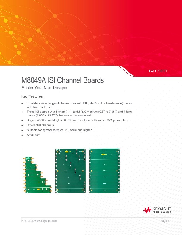
The M8049A ISI channel boards can be used to emulate channel loss in receiver test setups. The boards are designed to be used to emulate channel loss for data rates of 32 Gb/s and higher. A choice of 21 PC board traces with different lengths can be inserted into the signal path. The trace lengths range from 0.8 inch (20.3 mm) to 22.3 inch (566.4 mm). By cascading the traces within one board or with another board a wide range of channels can be emulated with very fine resolution of insertion loss steps. With their small size the ISI channel boards can be located closely to the device under test. The cascadable ISI channels are complemented by the Keysight Technologies, Inc. compliance channels for SATA, DisplayPort, PCI Express®.
Emulate Channel Loss
The channel loss between transmitter and receiver is a critical element for the receiver test for all electrical multi-gigabit serial interfaces. The channel loss depends primarily on the distance between transmitter and receiver and the electrical medium. The channel loss is typically defined by the S21 parameter in dB for certain frequencies. Many popular interface standards define the receiver test in a way that must include a certain channel loss in the test setup. M8049A offers a wide range of cascadable channels to emulate certain S21 loss characteristic in a repeatable and accurate way even for electrical interconnects using data rates of 32 Gbaud and higher.
Emulate frequency-dependent Attenuators
For testing the receivers in medium and long reach electrical interfaces, some standards such as IEEE 802.3cd and OIF-CEI-56G define so-called frequency dependent attenuators. These are used to emulate the channel loss characteristics of a worst-case channel that can occur in a transmission link. The M8049A ISI channel boards can be used to emulate such a frequency dependent attenuator for symbol rates above 10 Gbaud, e.g. you can emulate insertion losses between 1 and 20 dB with a single ISI trace for 16 GHz (corresponds to a 32 Gbaud link).
Emulate Inter-Symbol Interference
Rogers 4350B and Megtron 6 board material is used in many high-performance backplanes and server interconnects. Electrical cables are also very common (TBT, SAS, 100GBASE-CR4, 400GBASE-CR8) for the highest bandwidth of consumer, server, switch interconnects. With increasing bit rates the signal degradations caused by the channel becomes a critical element for the receiver characterization and compliance test. The so-called inter-symbol interference (ISI) caused by the channel degradation is a data dependent jitter or a bounded deterministic jitter. The ISI jitter added by a PC board trace not only depends on the trace length and the PC board material, but also depends on the data rate and the transmitted bit pattern. The ISI jitter a receiver must tolerate is typically defined in ps or in UI (unit intervals) by each standard for the required bit rate and compliance test pattern.