How to Characterize FET IV Curves

Measure FET Transfer Characteristics
Field-Effect Transistor (FET) IV characterization requires coordinated voltage sourcing and current measurement at the device gate and drain terminals. For a typical FET Id-Vg measurement, one channel applies a swept voltage to the gate while a second channel establishes the required drain bias. Current measurements are acquired at each voltage step to generate the transfer characteristic and show how drain current changes as a function of gate voltage. A dual-channel Source Measure Unit can perform the voltage-source and current-measurement functions synchronously, reducing the measurement configuration to a single instrument with two independently controlled channels. The gate channel is configured as a voltage source and stepped from a defined start voltage to a stop voltage while measuring current. The drain channel applies the required voltage bias and measures the corresponding drain current. For the example measurement configuration, the gate voltage is swept from 0 V to 2 V using 101 measurement points, corresponding to 20 mV steps, while the drain is maintained at 2 V across the same 101 points. Current compliance is configured independently for each channel, with a 1 µA limit on the gate channel and a 100 mA limit on the drain channel. The resulting FET IV characterization data can be plotted as gate voltage versus drain current to create the device's transfer characteristic. Linear or logarithmic graph scaling can then be selected depending on which portion of the transistor response needs to be examined. This synchronized semiconductor IV measurement configuration provides the voltage and current data needed for systematic transistor characterization.
Measurement configuration also requires appropriate range, timing, connection, and data-display settings. High Force and Low Force connections from each measurement channel are connected to the FET through a test fixture, with one channel controlling the gate and the other controlling the drain. The source terminal provides the common connection required for the measurement configuration. Once the device is connected, each channel can be configured independently for source function, source value, compliance limit, measurement parameter, sweep mode, sweep points, and triggering. Current measurement ranges can operate automatically or be fixed when a particular range is required. The demonstrated procedure, for example, shows how the minimum current measurement range can be changed to 10 nA and how measurement speed can be set to NORMAL, corresponding to an aperture time of one power line cycle. Trigger control can also synchronize both channels and introduce a defined measurement delay; the example configures a 100 ms measurement trigger delay and specifies that source and measurement trigger counts correspond to the number of sweep points. After the synchronized sweep is executed, the measured FET Id-Vg measurement can be displayed directly as an IV curve. The Y-axis can be switched between linear and logarithmic scaling to examine different current regions, while individual measurement values can be reviewed as a data list. Together, synchronized voltage sourcing, current measurement, compliance control, measurement-range selection, triggering, and graphical analysis form the complete measurement sequence for repeatable FET IV characterization using a precision Source Measure Unit.

FET IV Characterization Solution
See Block Diagram of FET IV Characterization Solution


Explore Products for Our FET IV Characterization Solution
-

![]()
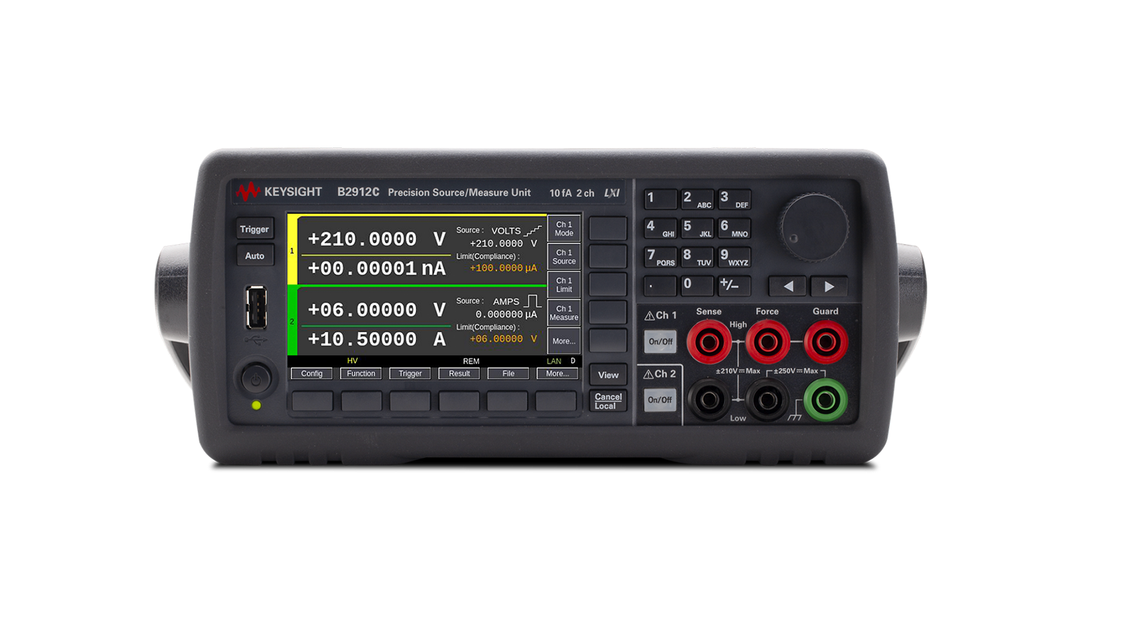
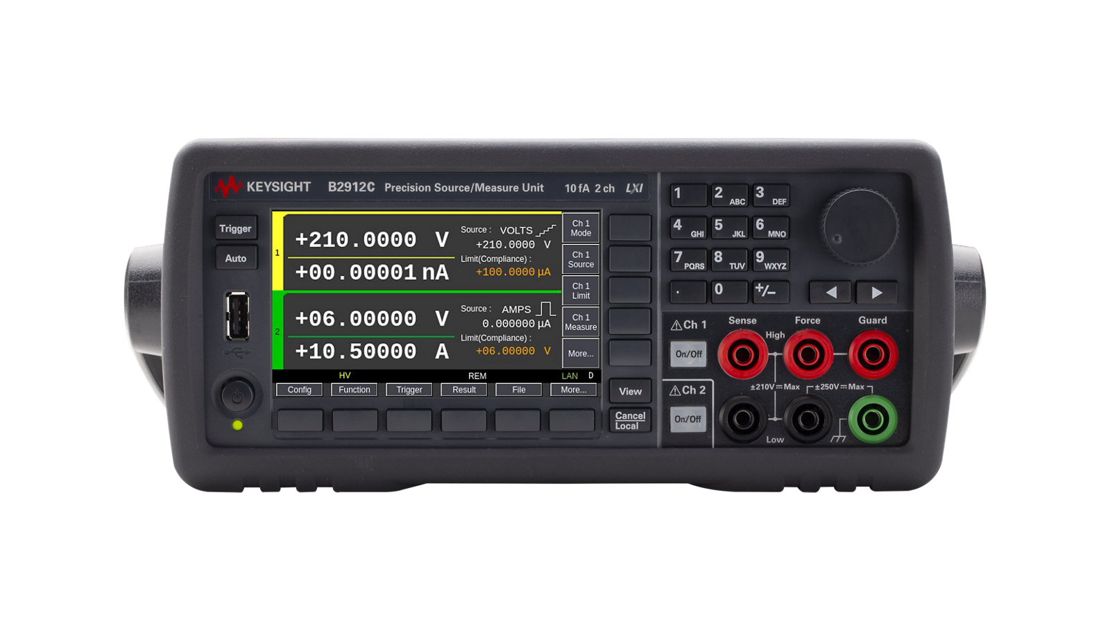
B2912C Precision Source / Measure Unit (2 ch, 10 fA)
-
![]()
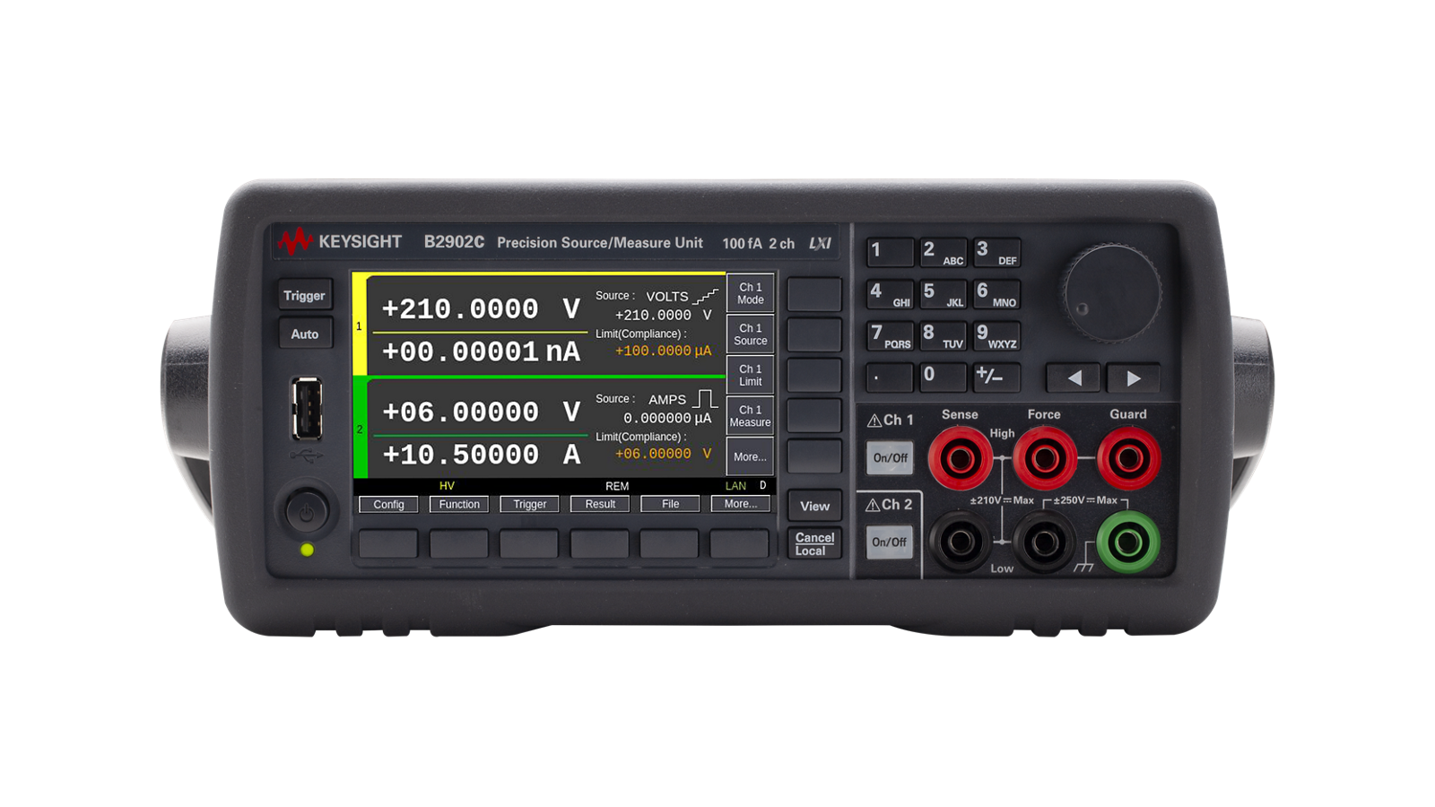
B2902C Precision Source / Measure Unit (2 ch, 100 fA)
-

![]()
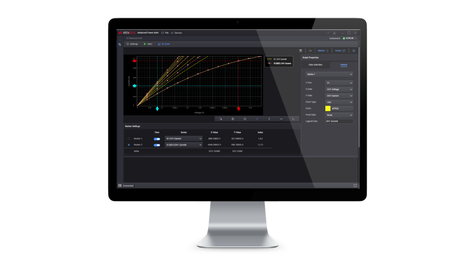
PW9251A PathWave IV Curve Measurement Software

Discover Resources and Insights
Additional Resources for Device Characterization
Related Use Cases


-
![]()
Learn More
How to Characterize VCSEL LIV Performance for 3D Sensing
Characterize VCSEL light-current-voltage behavior accurately using synchronized SMU measurements for high-throughput 3D sensing device testing.
Learn More

-
![]()
Learn More
How to Characterize Laser Diode Linearity
Measure laser diode linearity and detect kink phenomena using synchronized low-noise L-I-V characterization measurements.
Learn More
-
![]()
Learn More
How to Improve CMOS Reliability Testing
Perform comprehensive CMOS reliability testing with the Keysight B1500A Semiconductor Device Analyzer to evaluate gate dielectric integrity, hot carrier effects, bias temperature instability, and electromigration using a single integrated solution.
Learn More

Get in Touch with One of Our Experts
Need help finding the right solution for you?