Confirm Your Country or Area
Please Confirm
Confirm your country to access relevant pricing, special offers, events, and contact information.
What are you looking for?
N9952AU FieldFox Handheld Software

Software for a lightweight, durable cable and antenna analyzer, spectrum analyzer, network analyzer, and more
Starting from
Highlights
Enable deeper insights in measurement and analysis by expanding the capabilities of your FieldFox handheld analyzer with field-upgradeable software licenses. These capabilities are engineered to deliver benchtop results into the field.
- Handle routine maintenance and in-depth troubleshooting with one instrument
- Maximize performance with network analyzer, spectrum analyzer, built-in power meter, vector voltmeter, and more
- Order with a new instrument or upgrade an existing instrument
Spectrum Analysis
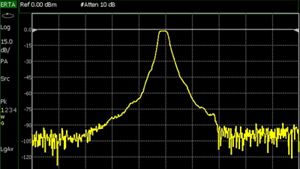

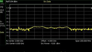
209 – Extended Range Transmission Analysis (ERTA)
Measure the scalar transmission gain or loss of waveguide systems, mixers, converters, and long cables where the two ends cannot easily meet.
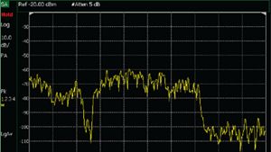

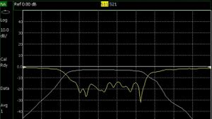
233 – Spectrum Analyzer
Perform high-performance spectrum analysis with four trace options, different detector types, radio standard selection, and flexible limit lines.
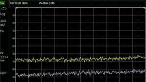

235 – Pre-amplifier
Increase spectrum analyzer sensitivity and reduce the DANL.
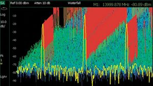
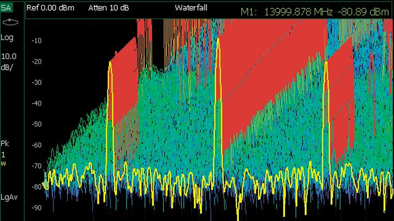
236 – Interference Analyzer and Spectrogram
Identify interfering signals quickly and accurately using spectogram or waterfall display. Record traces over time and store them for offline processing.
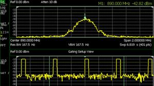

238 – Time Gating
Measure the spectrum of a periodic signal during a specified time interval.
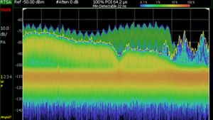
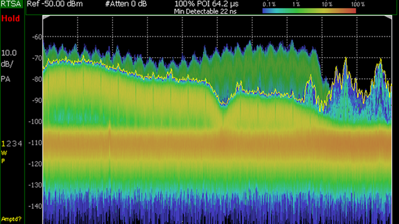
350 – Real-Time Spectrum Analyzer (RTSA)
Use gap-free, real-time spectrum analysis (RTSA) with 100 MHz of real-time bandwidth to capture small and intermittent signals masked by larger signals.
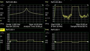
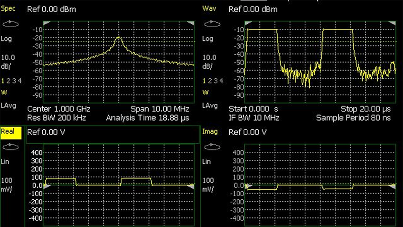
351 – I/Q analyzer (IQA)
Demodulate I/Q data and verify final signal chain integration or troublesoot signal quality degradation due to hardware or software issues.
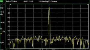

353 – IQ Streaming
Provide gapless IQ data to external application software to perform spectrum monitoring, demodulation, and decoding.
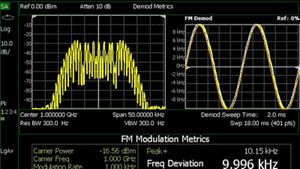
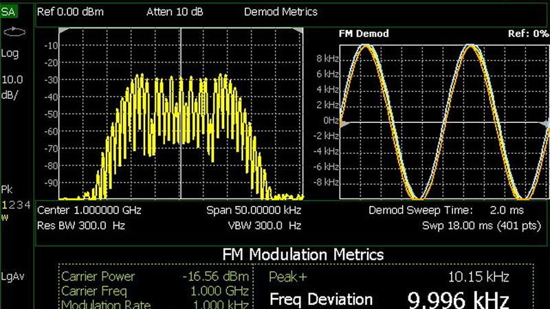
355 – Analog Demodulation
Demodulate and chracterize AM and FM signals of radio transmitters.
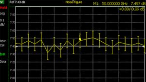
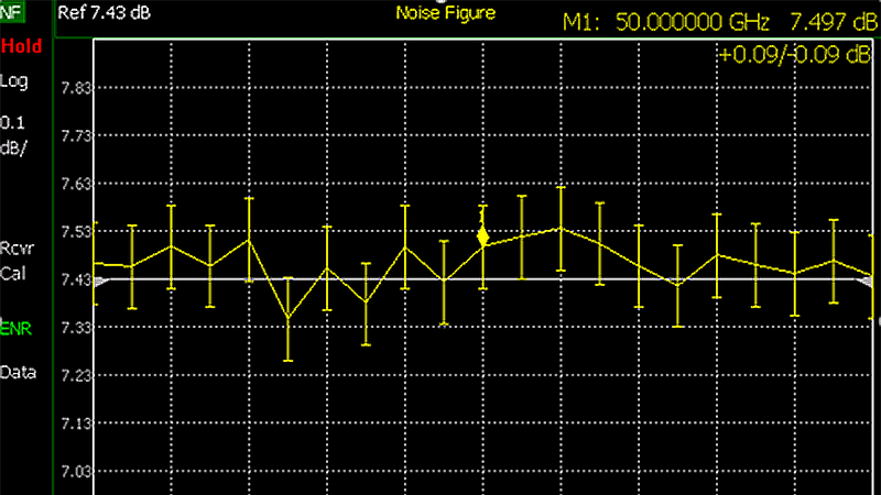
356 – Noise Figure
Characterize devices like low noise amplifiers, frequency converters, and receivers with portable, one-button Y-factor noise figure and gain measurements.
Cable, Antenna, & Network Analysis

010 – VNA Time Domain
Display reflection or transmission coefficients in the time domain and remove unwanted responses with time-domain gating.

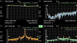
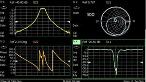
210 – VNA Transmission/Reflection
Use vector network analyzer mode to measure transmission and reflection (S21 and S11) magnitude and phase.
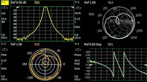

211 – VNA Full 2-Port S-Parameters
Enable vector network analyzer mode to measure all four S-parameters (S21, S11, S12, S22) magnitude and phase.

212 – 1-Port Mixed-Mode S-Parameters
Make balanced, mixed-mode S-parameter reflection measurements (Scc11, Sdd11, Scd11, Sdc11) with network analyzer mode.
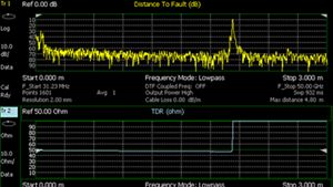

215 – TDR Cable Measurements
Identify the location and nature of faults alon cables using time-domain reflectometry measurements.
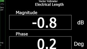

308 – Vector Voltmeter
Measure the phase shift and elctrical length of a device and view the results on the large display from a distance.
5G / LTE Field Test
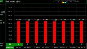

312 – Channel Scanner
Verify signal coverage, identify potential interference issues, and optimize network performance with channel power measurements of up to 20 channels at once.
358 – Electromagnetic Field (EMF) Measurements
Evaluate total RF exposure levels in any given area. Verify compliance to regulatory and government requirements using a triaxial isotropic antenna.
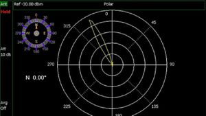

360 – Phased Array Antenna Support
Provide insights to available 4G cells at a given frequency or the component carrier for the LTE signals with Time Division Duplex frame structure.
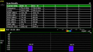
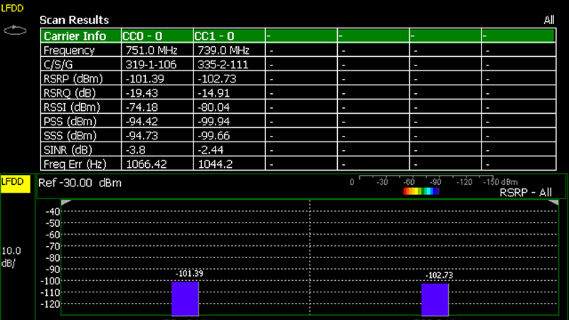
370 – Over-the-Air (OTA) LTE FDD
Analyze LTE FDD cell information transmitted over-the-air and optimize inter-RAT handovers for overlapping 5G and LTE networks.
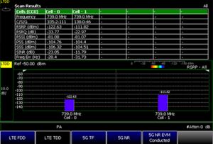

371 – Over-the-air (OTA) LTE TDD
Provide insights to available 4G cells at a given frequency or the component carrier for the LTE signals with Time Division Duplex frame structure.
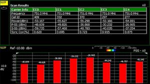
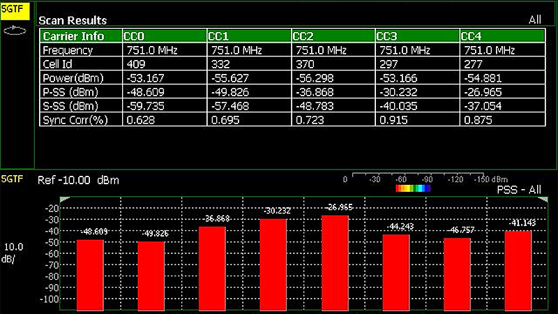
377 – Over-the-Air (OTA) 5G TF
Demodulate and analyze 5GTF cell information transmitted over-the-air from base station downlink multi-path and multi-cell environments.
Power Measurements

208 – USB Power Measurements versus Frequency
Characterize the scalar transmission response of devices such as mixers and converters using USB power sensor measurements versus frequency.

302 – USB Power Sensor Support
Characterize RF pulses such as those used in radar and electronic warfare systems using a USB peak power sensor.

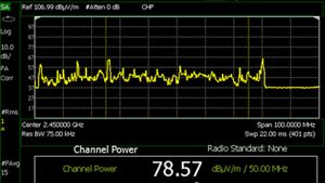
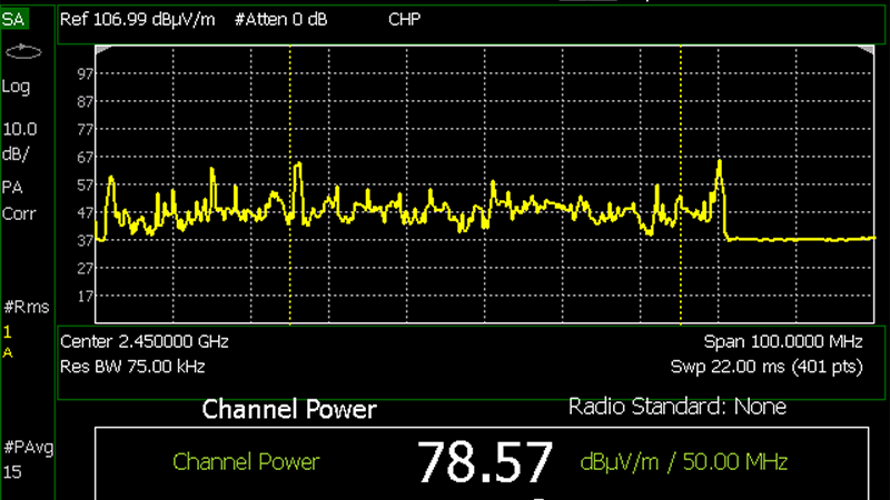
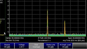
310 – Built-in Power Meter
Make accurate, user-definable channel power measurements such as transmitter output power with no additional external hardware.

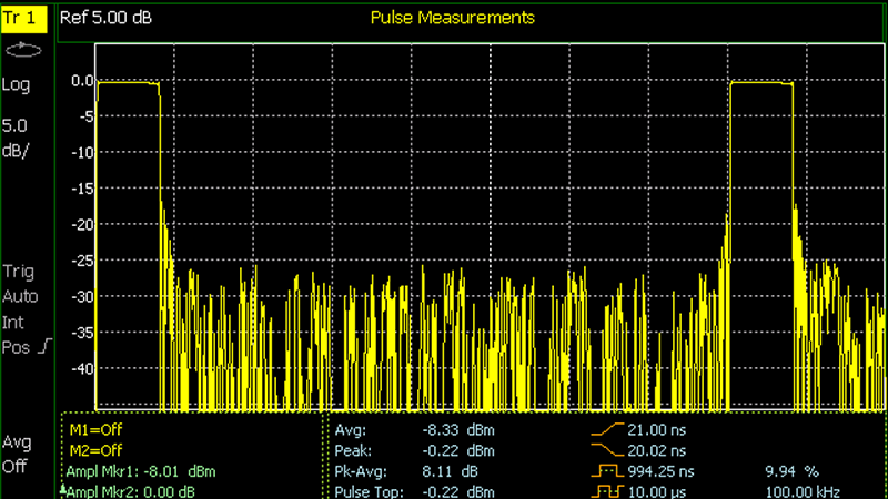
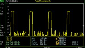
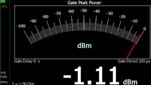
330 – Pulse Measurement with USB Peak Power Sensor
Efficiently characterize pulsed RF signals by leveraging a Keysight USB peak power sensor.
Utilities
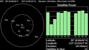

307 – GPS Receiver
Attach geolocation tags to measurements with a built-in GNSS/GPS receiver.

309 – DC Bias Variable Voltage Source
Provide power to amplifiers under test and bias tower mounted amplifiers.
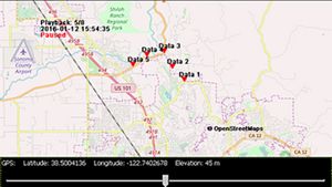
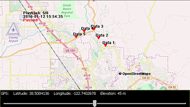
352 – Indoor and Outdoor Mapping
Import indoor and outdoor maps for data collection and plotting to the map.
Learn more about each software option in the Technical Overview.


Free Trials
- Get 30-day free trial license
- Enables option on your FieldFox
- Evaluate full-featured version with no functionality restrictions
Extend the Capabilities
Featured Resources


Want help or have questions?