
Modeling AM-to-AM Behavior
Technical Overviews
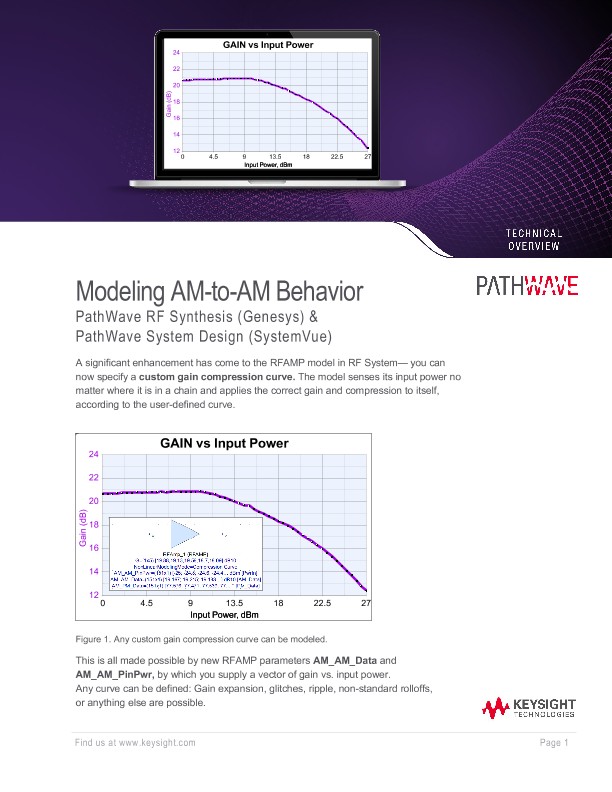
A significant enhancement has come to the RFAMP model in RF System— you can now specify a custom gain compression curve. The model senses its input power no matter where it is in a chain and applies the correct gain and compression to itself, according to the user-defined curve.
This is all made possible by new RFAMP parameters AM_AM_Data and AM_AM_PinPwr, by which you supply a vector of gain vs. input power. Any curve can be defined: Gain expansion, glitches, ripple, non-standard rolloffs, or anything else are possible This is all made possible by new RFAMP parameters AM_AM_Data and AM_AM_PinPwr, by which you supply a vector of gain vs. input power. Any curve can be defined: Gain expansion, glitches, ripple, non-standard rolloffs, or anything else are possible
As you acquire AM-to-AM (and corresponding AM-to-PM) data for your device model, keep the following guidelines in mind:
• Data can be entered either as absolute or relative (delta) gain values. Absolute gain is converted (silently) to relative gain inside the model, using the first point as the nominal smallsignal gain.
• Include data points from about 30 dB below to about 3 dB above P1dB.
• Use small power steps: 0.2 dB steps give higher accuracy than 0.5 dB steps.
• Employ techniques (e.g., IF bandwidth, averaging) to reduce noise in the data.
• Absolute gain data is preferred over relative because then both OP1dB and OPSat can be extracted automatically from the curve. If relative data are used, only IP1dB and IPSat are extracted, which may not provide all the behavior you need.
• In any case, 200 points are more than enough for good accuracy.
A breakthrough feature of the new model is the ability to extract P1dB and the odd-order intercepts like IP3, IP5, IP7, etc., from the gain compression curve. This technology was developed for Keysight vector network analyzers measuring device gain compression.
There is a “sweet spot” of the gain compression curve that results in the highest accuracy of extracted IP3. The device at left was swept from a low level to a few dB above P1dB. Even though the full curve is available for simulations, only a subset is used to extract IP3— from about 30 dB below to about 3 dB below P1dB. Any noise at the lowest levels is avoided, yet enough of the curve is retained for the extraction algorithm to perform well.
Glossary
AM-to-AM – the nonlinearity described by a gain compression curve, or Pout vs. Pin curve, where the device amplitude transfer function at higher input levels deviates from the corresponding function at low levels.
AM-to-PM – the nonlinearity in the phase transfer function at higher input levels deviates from the corresponding function at low levels.
Gain Expansion – a characteristic of some amplifiers whose gain rises before falling in compression.
IP3 – third-order intercept.
MATLAB Script – the language used by Pathwave System for calculations and post-processing.
MDIF – Measurement Data Interchange Format, an industry-wide format frequently used for simulation model data and that most test equipment (network analyzer, vector signal analyzer, etc.) uses to store and share measured data.
P1dB – 1 dB compression point.
Psat – Saturation power, typically the maximum power an amplifier can produce.
Sys-parameter – a parameter of a behavioral model that allows a user to specify a device characteristic (gain, noise figure, third-order intercept, impedance, etc.) versus frequency.