Resource Guide
How To Use An Oscilloscope – The Engineer's Guide


Introduction
Ever stared at a waveform that refused to settle and wondered if the problem was your circuit or the scope settings? Oscilloscopes can reveal exactly what’s happening in a signal, but only when you know how to set them up and read them clearly.
Many engineers struggle with unstable displays, confusing triggers, or measurements that don’t line up with expectations, and those issues can slow down development or point you in the wrong direction.
When you understand how to use a scope properly, you move through debugging faster, make better design decisions, and avoid chasing problems that aren’t really there. Strong oscilloscope skills help you diagnose noise, timing issues, or distortion with confidence.
In this guide, you will learn how to set up your scope, how to scale and trigger a signal, how to measure key parameters, and how to use advanced features when you need deeper insight. By the end, you’ll know how to capture clean, reliable waveforms and apply what you see to real engineering work.
Oscilloscope Basics You Need to Know
To read signals accurately, you need a clear picture of how an oscilloscope handles the information you feed into it.
A scope plots voltage over time. The vertical scale lets you adjust how much voltage each division represents, while the horizontal scale controls how much time appears across the screen. When you set these correctly, you get a waveform that’s easy to interpret instead of one that looks stretched, cramped, or distorted.
The trigger system plays a key role in stabilizing the display. Without it, the waveform slides around and becomes difficult to analyze. A proper trigger locks each cycle to the same starting point so you can measure rise times, compare pulses, or inspect noise with confidence. Many beginners rely only on auto trigger, but manual trigger level, edge selection, and single acquisition often reveal details that auto mode can miss.
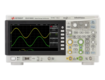
Once these elements are set, the waveform display shows the signal’s behavior in real time. You can see changes in amplitude, frequency, shape, and timing at a glance. Clear scaling and correct triggering ensure what you see on the screen matches what’s happening in the circuit.
Understanding these basics helps you avoid common misconceptions. Some users expect default settings to be “good enough,” but poor probe compensation, wrong coupling, or incorrect scaling can create misleading results. Others assume the scope will interpret the signal for them, when in reality the setup determines whether your measurements are trustworthy.
You don’t need advanced training to use a scope effectively. A working knowledge of voltage, current, and frequency is enough to start capturing clean, accurate waveforms. If you want a refresher on fundamentals, the Keysight oscilloscope basics guide offers a helpful overview and prepares you for the step-by-step instructions coming next.
Step-By-Step Instructions for Using an Oscilloscope
Once you understand the basic controls and how a scope displays signals, you can start capturing real measurements. The process is straightforward when you follow a consistent setup routine.
Before diving into the detailed steps, here’s a quick overview you can reference as you work.
Quick Steps for Setting Up, Probing, and Measuring
| Task | What You Do | Why It Matters |
|---|---|---|
| Connect probe to scope | Attach probe and set attenuation | Ensures correct scaling and signal integrity |
| Probe the signal | Connect probe tip and ground | Reduces noise and prevents ground issues |
| Power on and set coupling | Turn on scope and choose DC coupling | Allows full waveform viewing |
| Adjust scales | Set volts/div and time/div | Creates a readable waveform |
| Calibrate probe | Use calibration output | Prevents distorted or rounded waveforms |
| Set trigger | Choose trigger source and level | Stabilizes the display |
| Fine-tune display | Adjust scale, position, and cursors | Improves clarity and measurement accuracy |
| Measure parameters | Use measurement tools | Provides amplitude, frequency, and timing data |
| Record data | Save captures or screenshots | Supports reporting and debugging |
| Perform advanced tests | Use FFT, current probes, PWM tools | Expands your analysis capabilities |
Step 1: Connect the Probe to the Oscilloscope
Start by attaching the probe firmly to the input channel. A loose connector can cause intermittent readings, so give it a slight twist to confirm it’s locked in place.
Set the probe attenuation to 10X for most measurements because it reduces circuit loading and increases the effective bandwidth of your setup. Use 1X only when measuring very low-voltage, low-frequency signals.
If your scope supports probe detection, confirm the attenuation setting appears correctly on the screen. This prevents scaling errors later.
Step 2: Connect the Probe to Your Signal
Attach the probe tip to your test point and connect the ground clip to a solid ground reference. Keeping the ground lead as short as possible reduces ringing and noise pickup. If you’re working on a high-speed digital circuit, use a ground spring for cleaner edges.
Avoid clipping ground to a different section of the circuit than the reference node. Ground loops can distort the very signal you’re trying to measure.
Step 3: Turn On the Oscilloscope
Power up the oscilloscope and allow it to complete its initialization. Select your input channel and set it to DC coupling for general-purpose measurements. If you only want to view AC variations on a DC signal, switch to AC coupling to block the DC offset.
Once the channel is active, check that bandwidth limits and filtering settings are appropriate for the signal you expect.
Step 4: Set Vertical and Horizontal Scales
Use volts/div to size the waveform so it fills most of the screen without clipping. This improves resolution and makes fine details easier to see. Adjust time/div so you can view two to five cycles of the waveform.
Use vertical and horizontal position controls to move the waveform into a readable area. If the signal still looks too small or too large, use zoom functions (if available) to focus on specific sections.
Step 5: Calibrate the Probe
Attach the probe to the built-in calibration output, usually a 1 kHz square wave. Examine the shape:
- Rounded edges → under-compensated
- Pointed edges → over-compensated
- Flat tops and sharp corners → correct
Turn the probe’s adjustment screw until the waveform looks ideal. This step ensures accurate frequency response and prevents misleading signal shapes. If you switch probes or channels, recalibrate each one before making measurements.
Step 6: Set Trigger Mode
Set the trigger source to the channel you're using, then choose edge trigger on the rising or falling edge depending on the signal. Adjust the trigger level so the signal locks in place and repeats consistently.
If the waveform still moves:
- Try normal mode for stable, repetitive signals
- Use single-shot for capturing one-time events
- Adjust holdoff to stabilize complex digital patterns
Proper triggering is often the difference between a drifting mess and a clean, reliable waveform.
Step 7: Fine-Tune the Display
Once your waveform is stable, refine the view. Adjust volts/div and time/div until important features appear clearly. Use cursors for precise manual measurements or rely on the oscilloscope’s automatic measurement functions for quick results.
Check for details such as overshoot, ripple, sag, ringing, or distortion. If the display is still noisy, try:
- Shorter ground connection
- Bandwidth limit
- Averaging mode
- Higher-quality probe contact
These small adjustments can significantly sharpen the signal.
Step 8: Measure Basic Parameters
Use built-in tools to capture amplitude, RMS, frequency, period, and peak-to-peak values. Compare these readings to expected circuit behavior to verify proper operation.
If the waveform looks off, check:
- Power supply stability
- Component tolerances
- Interference or coupling from nearby circuits.
Step 9: Record and Analyze Data
Save screenshots or waveform data to the oscilloscope’s internal memory or a USB drive. Many scopes let you export data to software for deeper analysis.
Use features like:
- FFT to inspect noise, harmonics, or EMI sources
- XY mode for phase relationships
- Math functions to compare signals or remove offsets
Add notes or labels so your captured data tells a complete story when reviewed later.
Step 10: Advanced Measurements
Switch to specialized measurement modes when evaluating digital control signals or complex timing patterns. Pulse width, duty cycle, and rise/fall time tools are especially useful for switching regulators and PWM-based controls.
For current, use current probes or shunt resistors and configure scaling so your oscilloscope interprets the values correctly. If you’re analyzing high-speed digital or motor-control signals, fine-tune triggering and scaling to capture transitions cleanly.
Troubleshooting Common Oscilloscope Issues
Even with a correct setup, you may see waveforms that look unstable, noisy, or inconsistent. Most problems fall into a few predictable categories, and you can often resolve them quickly with a few adjustments.
Here are the most common issues and how to fix them.
Unstable Display
If the waveform drifts or jumps, the trigger settings are usually the cause. Confirm the trigger source matches your active channel, select rising-edge triggering, and adjust the trigger level until the waveform locks in place. If the signal still won’t stabilize, reduce the time/div setting or switch from auto to normal or single-shot mode to capture a more consistent event.
Noisy or Distorted Signal
Noise often comes from grounding or probe issues. Check that the probe is firmly attached, set to the correct attenuation, and grounded properly. Keep the ground lead short to reduce interference. Features like bandwidth limiting or averaging can help clean up the display, but addressing the probe connection usually delivers the biggest improvement.
Triggering Failure
If the oscilloscope can’t detect a stable trigger point, the signal may be too small or irregular. Increase the vertical scale to enlarge the signal and try a different trigger type. Pulse-width or pattern triggering works better for PWM or digital logic signals, while single-shot mode captures one-time events. Verify that you haven’t selected the wrong channel or coupling mode by mistake.
If the oscilloscope behaves inconsistently across channels or shows problems after basic checks, contact support for guidance or next steps. If these steps don’t resolve the issue, the oscilloscope may need calibration or service. This is where reliable, premium refurbished equipment with warranty and proper calibration becomes valuable.
Advanced Tips and Variations
Once you’re comfortable capturing stable waveforms, you can refine your approach to improve accuracy, speed, and insight. These advanced techniques help you get more out of your oscilloscope, especially when working with complex or rapidly changing signals.
- Optimize accuracy. Use 10X probes for most measurements to reduce loading and improve bandwidth, and switch to 1X only when you need maximum sensitivity on low-voltage analog signals. Disable bandwidth limits when you want the full frequency content of the signal, and use high-resolution or averaging modes to reduce noise. Keeping probe leads short, especially on fast edges, prevents distortion and ringing.
- Improve speed and efficiency. Automatic measurements save time and reduce human error, especially when you're tracking multiple parameters like frequency, rise time, and peak-to-peak voltage. A measurement table lets you monitor these values in real time. Saved setups or presets help when you run the same tests repeatedly. If you work with embedded systems, enable digital protocol decoding so the scope interprets I²C, SPI, UART, CAN, or LIN data directly from the waveform.
- Use alternative acquisition modes. Envelope mode shows minimum and maximum variations to reveal jitter or instability over time. Peak detect captures narrow glitches that standard acquisition may miss. Equivalent-time sampling helps you visualize very high-frequency repetitive signals even when real-time bandwidth is limited. When you need frequency-domain insight, FFT mode exposes harmonics, noise sources, and EMI behavior that aren’t obvious in the time domain.
- Customize for specific applications. Switching power supplies and PWM systems benefit from trigger holdoff adjustments to stabilize complex patterns. Multi-channel systems require time-skew compensation so simultaneous events display correctly. Math functions let you subtract channels, calculate power, evaluate duty cycle, or compare phase. XY mode helps visualize nonlinear relationships or phase shifts between two signals.
By weaving these advanced techniques into your workflow, you turn your oscilloscope into a faster, more precise problem-solving tool that adapts to whatever your project demands.
Real-World Applications
Oscilloscopes play a central role in everyday engineering tasks, from early-stage prototyping to final product validation. When debugging a new circuit, a scope helps you see whether power rails are stable, confirm timing relationships, or spot unexpected noise that causes intermittent failures.
Engineers working with microcontrollers rely on oscilloscopes to verify clock accuracy, measure pulse widths, and monitor communication buses while firmware runs. In automotive environments, scopes help diagnose ignition timing, sensor behavior, and PWM-driven control systems that standard meters can’t capture.
Many teams see immediate workflow improvements once they use an oscilloscope more intentionally. A prototype developer might cut hours from a debugging cycle by catching a subtle voltage drop that only appears under load. A firmware engineer can validate interrupt timing or communication latency without guesswork. In one project, a test engineer resolved a long-standing EMC issue after switching to FFT mode and identifying a noise source no other tool revealed.
Real-world challenges often involve noisy environments, fast edges, or complex digital patterns. These issues become manageable when you apply proper triggering, grounded probing, and the right acquisition mode. As you gain experience, the oscilloscope becomes not just a measurement tool but a way to understand how your design behaves under real conditions
Additional Resources
A few essential tools and accessories can make your oscilloscope work more accurately and efficiently. Different probe types, such as passive 10X probes, active high-bandwidth probes, differential probes, and current probes, help you match the measurement method to the signal you’re analyzing.
A reliable signal generator is also useful when you need a clean reference signal for testing or calibration, especially during early prototyping or validation work. Accessories like probe ground springs, BNC adapters, and high-quality coax cables round out a solid measurement toolkit.
For deeper learning, several high-quality resources can help you expand your skills. You can explore detailed guides, application notes, and training videos to build confidence in both time-domain and frequency-domain analysis. Tutorials from engineering education platforms, technical blogs, and trusted instrumentation providers provide step-by-step demonstrations and practical examples.
It also helps to stay connected with other engineers. Active online communities offer real-world advice, troubleshooting help, and shared project experiences. Places like the EEVblog Forum, All About Circuits, and Reddit’s r/ECE host discussions on measurement techniques, equipment selection, and debugging strategies. Participating in these spaces keeps you up to date with best practices and exposes you to solutions you might not encounter on your own.
Conclusion
Learning to use an oscilloscope with confidence gives you clearer insight into how your circuits behave and helps you solve problems faster. You now know how to connect probes correctly, scale and trigger your waveform, capture clean measurements, and apply advanced features when you need deeper analysis. These skills make every stage of development more efficient and more reliable.
Mastery comes with hands-on practice. The more you explore different signal types, acquisition modes, and measurement functions, the easier it becomes to recognize patterns, spot issues, and confirm performance. Consistent use builds intuition and helps you move through design and troubleshooting with greater speed and accuracy.
At the Keysight Used Equipment Store, you can access Premium Used instruments, including oscilloscopes, network analyzers, and VNAs. Each device delivers like-new performance with OEM calibration, extended warranties, and expert technical support for complete peace of mind.
Act now to explore high-quality refurbished equipment from Keysight and bring precision, reliability, and measurable confidence to your next project.
Whenever You’re Ready, Here Are
5 Ways We Can Help You
Browse our premium used network analyzers, oscilloscopes, signal analyzers and waveform generators
Call tech support US: +1 800 829-4444
Press #, then 2. Hours: 7am – 5pm MT, Mon– Fri
Contact our sales support team
Create an account to get price alerts and access to exclusive waitlists
Talk to your account manager about your specific needs.
FAQs
How does an oscilloscope work?
An oscilloscope measures voltage over time and displays it as a waveform. The input signal is sampled, processed, and shown on the screen so you can analyze amplitude, timing, shape, and frequency.
What are the main parts of an oscilloscope?
Key components include input channels, the display screen, vertical and horizontal controls, trigger settings, and measurement tools. Many models also include math functions, acquisition modes, and USB or LAN ports for saving data.
How do I connect and calibrate an oscilloscope probe?
Attach the probe tip to the test point and connect the ground clip to the circuit ground. Then connect the probe to the oscilloscope’s calibration output and adjust the probe’s compensation screw until the calibration square wave has flat tops and sharp edges.
What is triggering and why is it important?
Triggering locks the waveform to a consistent starting point so it doesn’t drift on the screen. It’s essential for capturing repetitive signals, analyzing edges, and stabilizing irregular waveforms.
How do I set vertical and horizontal scales?
Use volts/div to size the waveform vertically and time/div to display a clear number of cycles horizontally. Adjust the position knobs to center the waveform and use zoom features when you need more detail.
Can an oscilloscope measure both AC and DC signals?
Yes. Use DC coupling to view the entire waveform including any DC offset, and AC coupling to block the DC component when analyzing small AC variations.
What safety precautions should I take using an oscilloscope?
Always connect the ground clip to a proper reference point, avoid creating ground loops, and be cautious with high-voltage or floating circuits. Use the correct probes and accessories for the voltage and bandwidth you’re measuring.
How do I measure frequency and pulse width with an oscilloscope?
You can use the scope’s automated measurement features or place cursors manually to read frequency, period, duty cycle, and pulse width. Scaling and triggering should be stable before taking these measurements.
What maintenance does an oscilloscope require?
Clean probe tips and connectors periodically, check probe compensation, and ensure the instrument receives regular calibration. Store probes properly to avoid cable damage and signal drift.
How do I troubleshoot common oscilloscope issues?
Confirm the probe is connected securely, verify the trigger source and trigger level, and adjust volts/div or time/div to bring the waveform into view. If the signal still looks incorrect, check grounding, probe attenuation settings, and the health of the input signal itself.