
Tech Guides
How To Measure Antenna Gain Using a Network Analyzer



Introduction
Two engineers measure the same antenna and report gains 2.15 dB apart. Both measurements are correct. If you work with RF systems, antenna gain helps decide how far your link reaches and how much power that reach costs. Measuring it correctly is another matter: gain is a radiated quantity, so it typically takes 2 antennas, a known geometry, and a calibrated instrument to measure. A vector network analyzer (VNA) is a standard bench instrument for the job, because one calibrated S21 measurement captures the transmit-to-receive path. This guide covers what antenna gain is, the standard ways to measure it, and a step-by-step VNA procedure aligned with published methods.
Summary
- Antenna gain = directivity x radiation efficiency (per IEEE Std 145): how strongly an antenna concentrates power in its peak direction, accounting for internal losses. Units: dBi (relative to an isotropic radiator) or dBd (relative to a half-wave dipole), with dBi = dBd + 2.15.
- The standard methods: the gain-transfer (gain-comparison) method using a reference antenna of known gain, and the absolute two-antenna and three-antenna methods built on the Friis transmission equation. No reference antenna is needed for the absolute methods.
- A VNA measures gain through S21 (transmission between 2 antennas) after a calibration; it also checks the antenna's match through S11 before any gain number is meaningful.
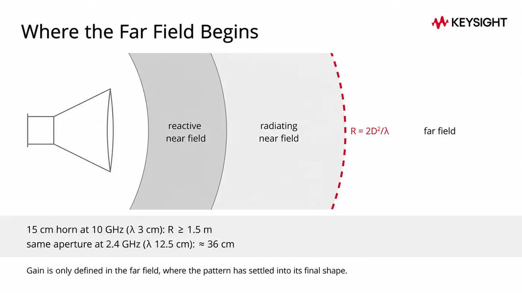
- Measure in the far field: separation R of at least 2D²/λ (D = largest antenna dimension, λ = wavelength), and clean up reflections with absorber or time-domain gating.
- Certified used analyzers that fit the job: the ENA E5080B (options up to 53 GHz), the E5071C (options up to 20 GHz), the value E5063A for antenna and passive test, and the FieldFox N9952B for field work, with Keysight Used savings of 40 to 90% below new list and up to 5 years warranty options.
Short on time? Browse the certified used network analyzers and request a quote.
What Is Antenna Gain?
Antenna gain describes how well an antenna converts input power into radio waves concentrated in a specific direction. Higher gain usually means a more focused radiation pattern, a stronger signal in that direction, and a narrower beam.
Gain combines two separate properties into one number, and IEEE Std 145, the standard for antenna terms, defines the relationship:
- Directivity measures how strongly the radiation pattern concentrates power in the peak direction compared with an ideal antenna radiating equally in all directions. It is a property of the pattern shape alone.
- Radiation efficiency is the fraction of input power the antenna radiates rather than loses to conductor and dielectric heating.
- Gain = directivity x radiation efficiency. Gain is always less than or equal to directivity, because no real antenna is lossless.
Beamwidth is the trade-off: a higher-gain antenna concentrates power into a narrower beam, usually described by the half-power beamwidth, the angle across which the pattern stays within 3 dB of its peak. Directivity and beamwidth are determined from the measured radiation pattern. Neither has a single universal formula independent of that pattern, which is why gain is measured rather than calculated for real hardware.
What Are dBi and dBd?
Antenna gain is often quoted in two decibel units, and mixing them up shifts the number by 2.15 dB:
| Unit | Reference | Meaning |
|---|---|---|
| dBi | Isotropic radiator | Gain relative to a lossless, theoretical antenna radiating equally in all directions. An isotropic radiator cannot be built; it is the mathematical reference. |
| dBd | Half-wave dipole | Gain relative to a half-wave dipole. A lossless half-wave dipole has a directivity of 1.64, which is 2.15 dB above isotropic. |
| Conversion | dBi = dBd + 2.15 | 0 dBd = 2.15 dBi; the offset is a fixed constant. |
That is how two engineers can measure the same antenna correctly and still report gains 2.15 dB apart: one quotes dBi, the other dBd. A worked comparison: an antenna specified at 5 dBd has an absolute gain of 7.15 dBi. Against a 3 dBi antenna, the difference is 4.15 dB, which is a factor of about 2.6 in radiated power density in the peak direction, not "more than twice the power" in a total power sense: gain redistributes power, it does not create it.

How Do You Measure Antenna Gain?
Most standard gain measurements share one basic setup: a transmitting antenna and a receiving antenna at a known separation, with the transmission between them measured precisely. The methods differ in what you assume known. IEEE Std 149, the recommended practice for antenna measurements, defines the categories this article follows: gain-transfer (comparison against a known reference antenna) and absolute methods (two-antenna and three-antenna, no reference needed).
Antenna efficiency affects gain directly: an efficient antenna radiates more of its input power, so efficiency losses pull gain below directivity. The measurement environment matters too, since reflections from buildings, fixtures, and the ground can distort the measured pattern.
Before using any method, two conditions must be met:
- Far-field separation. Gain is defined where the radiated wave has settled into its final pattern shape. The standard criterion: separation R of at least 2D²/λ, where D is the largest dimension of the larger antenna and λ is the wavelength (with R also much larger than both D and λ). Worked example: a 15 cm horn at 10 GHz (λ = 3 cm) needs R of at least 2 x (0.15)² / 0.03 = 1.5 m; the same aperture at 2.4 GHz (λ = 12.5 cm) gives only about 36 cm, under 3 wavelengths, so there the "much larger than both D and λ" condition sets the minimum spacing instead.
- A controlled environment. Anechoic chambers absorb reflections; open-area test sites control them by geometry; a bench measurement can approximate both by using absorber panels and the VNA's time-domain gating to cut reflected paths out of the response. NIST’s antenna metrology laboratory, which operates the national antenna calibration service, runs robotic free-space measurement systems covering roughly 0.1 GHz to 500 GHz.
See E5080B Special Offers
Direct Comparison Method (Gain Transfer)
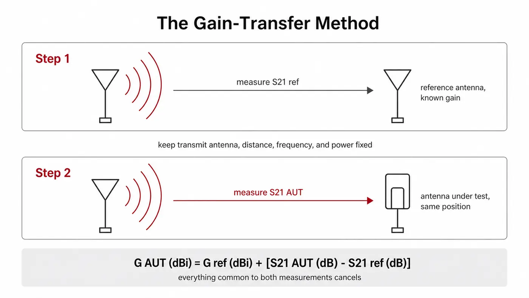
The gain-transfer method, also called the gain-comparison or direct comparison method, measures your antenna against a reference antenna whose gain is already known, typically a standard-gain horn with a calibrated, traceable gain value.
The procedure is straightforward: keep the transmit antenna, distance, frequency, and power fixed. Measure the received level with the reference antenna, then swap in the antenna under test (AUT) at the same position and measure again. The gain follows from substitution:
Formula Placeholder
The subtraction cancels everything common to both measurements (transmit antenna gain, path loss, cable losses), which is what makes the method useful: only the difference between the two received levels and the reference antenna's known gain enter the result.
Practical drawbacks:
- The result is only as good as the reference antenna's calibration, so the reference needs a traceable gain value.
- The AUT must sit in the same position the reference occupied; placement errors show up directly in the result, especially when the two antennas differ in size.
- Each frequency band needs a reference antenna that covers it.
Absolute Gain Method (Two-Antenna and Three-Antenna)
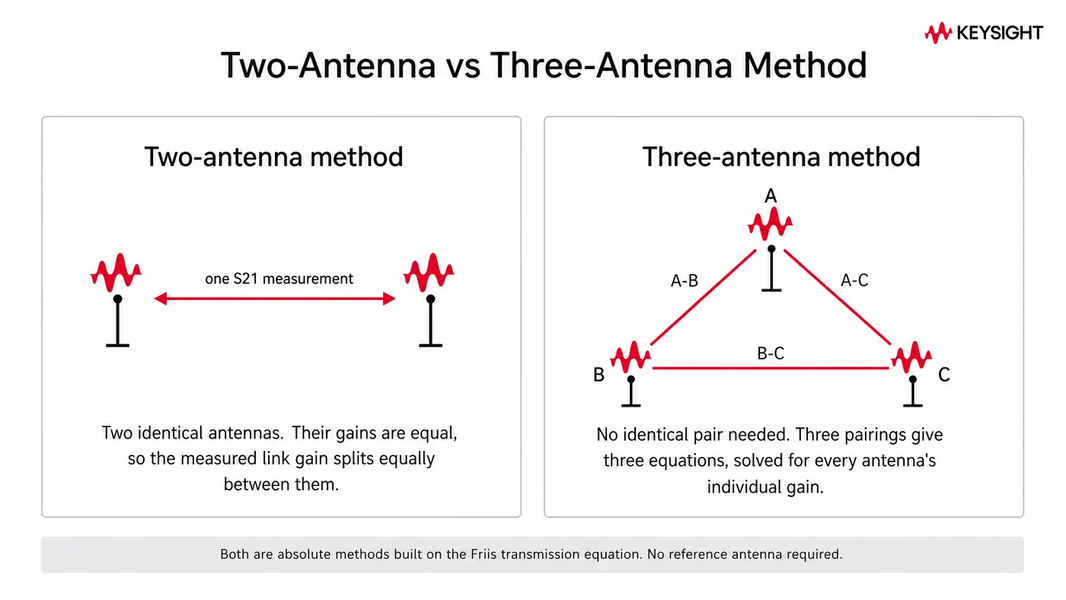
The absolute methods need no reference antenna. They solve the Friis transmission equation, first published by H. T. Friis in 1946, which relates received to transmitted power between two matched, aligned antennas in free space:
Formula Placeholder
Measured on a VNA, P_r/P_t is |S21|², so in decibels the sum of the two gains equals the measured S21 plus the free-space path loss term 20 log10(4πR / λ).
- Two-antenna method: use two identical antennas. Their gains are equal, so one S21 measurement solves for gain: G = 1/2 x [S21 (dB) + 20 log10(4πR / λ)].
- Three-antenna method: when no two antennas are identical, measure all three pairings (A-B, A-C, B-C). Three equations, three unknown gains, solved simultaneously; each antenna’s gain can be solved without assuming any one of them is known.
The assumptions are the error budget: free-space far-field conditions, impedance-matched ports, and aligned polarization. Each violated assumption (multipath, mismatch, polarization skew) lands directly in the measured gain, which is why the setup conditions above matter more than the algebra.
How Do You Use a Network Analyzer To Measure Antenna Gain?
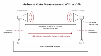
A vector network analyzer is well suited to these methods because it supplies the stimulus and measures the response in one calibrated instrument: S11 for the antenna's match and S21 for the transmission between two antennas, both as magnitude and phase across a swept frequency band. Keysight's application note Understanding the Fundamental Principles of Vector Network Analysis covers the S-parameter framework; the companion field-measurement note, Techniques for Precise Cable and Antenna Measurements in the Field, covers separating cable and connector effects from true antenna behavior.
The basic procedure is:
| Step | What to do | Why it matters |
|---|---|---|
| 1. Plan the geometry the analyzer | Compute the far-field distance (2D²/λ) for your larger antenna at the highest test frequency; mount both antennas at that separation or more, aligned and co-polarizedthe antenna is properly connected to the analyzer via a coaxial cable. The cable will run from the analyzer's output port to the antenna's input port. | Gain is only defined in the far field; misalignment and polarization skew read as lost gain |
| 2. Calibrate the analyzer | Run a 2-port calibration (SOLT mechanical or ECal) at the ends of your test cables, or a response/thru normalization for comparison measurements | Calibration moves the measurement reference plane to the antenna connectors, removing cable loss and analyzer systematic errors |
| 3. Set the sweep | Set start and stop frequencies spanning the antenna's operating band, with enough points for the band's detail | Gain varies with frequency; a single-frequency number can hide the curve |
| 4. Set source power | A moderate source level (for example -10 to -20 dBm) is a common starting point for passive antenna work | High enough for a clean trace above the noise floor, low enough to avoid receiver compression at short range |
| 5. Check the match first | Measure S11 of the AUT; note the return loss across the band | A badly matched antenna reflects power back; mismatch loss corrupts the gain result and shows up here first |
| 6. Measure the transmission | Measure S21: reference antenna first, then swap in the AUT (gain transfer), or between identical antennas (two-antenna), or all three pairings (three-antenna) | S21 is the calibrated transmission measurement used in each gain formula |
| 7. Clean up and compute | Apply time-domain gating or add absorber if the S21 trace shows ripple from reflections; then apply the method's formula | Multipath ripple is a common bench-measurement error; gating isolates the direct path |
Record the frequency, separation, and polarization with the result: a gain number without its measurement conditions is hard to compare.
Reliability in Every Reading
What Are the Benefits of Measuring Antenna Gain With a Network Analyzer?
You can also assemble a gain measurement from a signal generator driving the transmit antenna and a spectrum analyzer reading the received level. The comparison is worth making clearly:
- A generator-plus-spectrum-analyzer pair measures scalar received power. It works for substitution measurements, can support very long ranges (the two instruments need no cable between them), and uses instruments many benches already own. The trade-offs: two instruments to configure, amplitude-only data, and no vector error correction, so cable and mismatch effects need to be accounted for separately.
- A vector network analyzer puts source and receiver in one calibrated instrument: one calibration covers the path, S11 and S21 come from the same connection, and time-domain gating can help remove reflected paths from the measurement. The limit: both antennas connect to the same instrument, so very long-range outdoor measurements need long cables or a different approach.
For bench and chamber work at typical separations, the VNA's calibrated, phase-aware S21 measurement is often the more direct route to a defensible gain number, and the same instrument then covers return loss, VSWR, and impedance work across later antenna checks and troubleshooting. For the wider instrument comparison, see the network analyzer versus spectrum analyzer guide.
Which Keysight Network Analyzer Fits Antenna Gain Measurement?
Match the analyzer to your frequency band and where you measure. Frequency ranges below are from the official Keysight product pages.
| Need | Keysight model | Family | Frequency range | Ports |
|---|---|---|---|---|
| Benchtop antenna and passive test, value | E5063A | ENA | 100 kHz to 18 GHz | 2 |
| Workhorse S-parameters, certified used | E5071C | ENA | Options from 9 kHz up to 20 GHz maximum | 2 or 4 |
| Benchtop ENA with R&D performance, widest reach | E5080B | ENA | Options from 9 kHz up to 53 GHz maximum | 2 or 4 |
| Microwave and mmWave-adjacent metrology | N5225B | PNA | Up to 50 GHz | 2 or 4 |
| Field and tower antenna work, handheld | N9952B | FieldFox | 300 kHz to 50 GHz | 2-port VNA + CAT modes |
| Field work to 18 GHz | N9917B | FieldFox | 30 kHz to 18 GHz | CAT standard, VNA optional |
The certified used instrument we highlight is the ENA E5080B: a benchtop ENA with R&D performance and options reaching 53 GHz, up to 140 dB dynamic range (frequency- and option-dependent), and time-domain analysis available for the gating step (confirm the installed options per unit). The E5071C (options up to 20 GHz) is a certified-used workhorse that currently has good availability; Keysight has retired it as a new instrument in favor of the E5080B, which can make certified used a practical route to that platform. Keysight also publishes PNA-based antenna measurement techniques for antenna-range work on the PNA N5225B class. For tower and site work, the FieldFox N9952B features a full 2-port VNA mode plus cable-and-antenna test in one battery-powered handheld. One housekeeping note: this page previously promoted the E5072A, which Keysight has since retired (its named successor is the E5081A ENA-X); the models above are the current recommendations.
A word on buying used for this job: gain measurement depends on calibration, so the analyzer's calibration history matters alongside its specifications. Certified used analyzers from Keysight are inspected, Keysight-calibrated with traceable results, and covered by up to 5 years warranty options, and Keysight Premium Used units also pass a final 101-point quality check. Keysight Used units are priced 40 to 90% below new list. That supports the measurement confidence this procedure depends on, while lowering capital cost compared with buying new.
Closing Thoughts From Keysight
Antenna gain measurement depends more on disciplined setup than specialized equipment: respect the far-field distance, calibrate to the antenna connectors, check the match before relying on the gain result, and control reflections with absorber or gating. With those conditions met, a two-port VNA and either a calibrated reference antenna or a pair of identical antennas produce gain numbers you can defend against IEEE Std 149's methods.
If you are choosing the instrument, the model table above maps each band and setting to a certified-used analyzer. Browse the certified used network analyzers, or ask us to confirm a unit's frequency options and calibration status before you request a quote or purchase.
Whenever You’re Ready, Here Are
5 Ways We Can Help You
Browse our certified used network analyzers, signal analyzers, and signal generators
Ask us to confirm a unit's frequency options, time-domain capability, and calibration status before you buy
Call tech support US: +1 800 829-4444 (Press #, then 2. Hours: 7am to 5pm MT, Mon to Fri)
Create a Used Equipment Portal account, free of charge, for saved favorites and stock alerts
Talk to your account manager about your antenna measurement setup
The Used Equipment Store newsletter carries new-stock notices and guides like this one.