Resource Guide
Understanding How Transistors Work: A Guide for Electrical Engineers


Introduction
Picture a prototype circuit that runs fine in simulation but fails on the bench. Switching is erratic, amplifiers distort, and hours are wasted hunting the cause.
Often, the problem comes down to the transistor itself: using the wrong specs, setting the bias incorrectly, or overlooking how the device behaves in real conditions.
Most engineers know transistors act as switches or amplifiers. But real success comes from understanding the finer details such as current flow, gain, and saturation. These factors decide whether a circuit runs flawlessly or needs constant rework.
This guide breaks down transistor operation step by step, from structure and biasing to troubleshooting and advanced design tips, so you can choose the right device, solve problems quickly, and build more reliable circuits. For related measurement skills, see our Oscilloscope Basics Guide.
Background and Context
A transistor is a semiconductor device that uses a small current or voltage at one terminal to control a larger current through others. Its operation is built on the PN junction, the boundary between positively and negatively doped semiconductor regions. In a BJT, these junctions form the emitter, base, and collector. In a MOSFET, they form the source, gate, and drain.
Transistors are at the core of modern electronics. Early circuits used them as single components, but today billions are built into every microprocessor. Global production now exceeds one quintillion devices each year. They serve as digital switches, analog amplifiers, and power regulators across nearly every field of electronics.
Despite their importance, several misconceptions still cause design errors:
- Transistors are only simple on-off switches.
- All BJTs behave the same in every circuit.
- MOSFETs always outperform BJTs.
- Current always flows in the same direction regardless of type.
- Small changes in biasing do not matter.
In practice, analog characteristics such as gain, frequency response, and saturation are just as important as digital switching. Even small variations in device parameters or biasing can dramatically affect performance.
To get the most from this guide, you should already be comfortable with circuit theory and semiconductor basics. With that foundation, you will be able to build on the deeper explanations here and avoid common pitfalls in transistor design.
Step-by-Step Instructions: How Transistors Work
Understanding how a transistor operates requires breaking down its behavior into clear stages. Each stage builds on the previous one, from semiconductor physics to circuit-level applications.
Below is a structured walkthrough designed for engineers who want both the physical intuition and the practical verification methods.
Summary of Transistor Operation Steps
| Step | Focus | Difficulty | Time Needed |
|---|---|---|---|
| 1 | Understanding the PN junction | Basic | 5–10 minutes |
| 2 | Exploring biasing conditions | Intermediate | 15–20 minutes |
| 3 | Current flow in active mode | Intermediate | 20–25 minutes |
| 4 | Switching behavior (cutoff/sat.) | Advanced | 20–25 minutes |
| 5 | Practical verification methods | Applied | 30 minutes+ |
Step 1: Understanding the PN Junction
At the core of any transistor lies the PN junction. In a BJT, two such junctions form the emitter-base and base-collector regions.
Charge carriers (electrons or holes) move across these junctions depending on how they are biased. Forward bias reduces the barrier, allowing carriers to flow; reverse bias raises it, blocking current.
Tip: Always note the doping levels. A heavily doped emitter injects carriers efficiently, while the lightly doped base controls the transistor’s gain.
Expected outcome: You should be able to explain why current flows in one direction across a junction and how this forms the basis of amplification.
Step 2: Exploring Biasing Conditions
The way a transistor is biased determines how it behaves in a circuit.
- Active mode: The base-emitter junction is forward biased and the base-collector junction is reverse biased. In this state, the transistor amplifies current.
- Cutoff mode: Both junctions are reverse biased, so no current flows.
- Saturation: Both junctions are forward biased, and the transistor behaves like a closed switch.
For MOSFETs, biasing the gate-source voltage relative to the threshold determines conduction.
⚠️ Warning: Incorrect biasing can lead to problems such as thermal runaway or even permanent damage.
How to check: Use a multimeter or oscilloscope to measure the voltages across the terminals and verify they match the intended operating mode.
Step 3: Current Flow in Active Mode
In a BJT, a small base current controls a much larger collector current. This is quantified by the current gain (β). In a MOSFET, the gate voltage creates an electric field that modulates channel conductivity without requiring steady-state gate current.
Design note: BJTs are current-controlled, MOSFETs are voltage-controlled. Choose based on application needs.
Expected outcome: You should understand how a transistor amplifies signals by controlling a large current with a small input.
Step 4: Switching Behavior (Cutoff and Saturation)
When driven into cutoff, the transistor effectively disconnects the load. When pushed into saturation, it creates a low-resistance path, like a closed switch. These two extremes form the foundation of digital logic.
Tip: Minimize switching losses by driving the base (or gate) strongly enough to ensure rapid transitions.
Verification: Monitor rise and fall times with an oscilloscope to evaluate switching performance.
Step 5: Practical Verification Methods
Engineers rarely stop at theory. To validate transistor behavior:
- Use an oscilloscope to observe voltage and current waveforms across terminals.
- Apply known signals and measure amplification or switching thresholds.
- Cross-check against datasheet parameters such as saturation voltage, maximum ratings, and switching speed.
For further reference, see the ROHM Semiconductor Transistor Explanation.
Troubleshooting Transistor Circuits
Common issues such as a switch not turning on, distortion in an amplifier stage, or overheating in a power circuit often trace back to fundamental causes: incorrect biasing, component mismatch, or thermal stress.
Recognizing the problem quickly and applying a systematic approach saves time and prevents damage to the rest of the system.
- No switching: If a transistor fails to turn on, check whether the base or gate drive is sufficient. In BJTs, inadequate base current leaves the device stuck in cutoff. In MOSFETs, a gate voltage below threshold will block conduction. Always verify with a meter or oscilloscope to confirm correct voltage levels.
- Distortion: In amplifier circuits, distortion typically results from improper biasing, driving the transistor too close to cutoff or saturation. Revisit the bias network and ensure that quiescent current settings match the design requirements.
- Overheating: Excessive power dissipation or inadequate heat sinking leads to rapid temperature rise. This not only alters electrical characteristics but can cause permanent failure. Always check the device’s maximum ratings and consider thermal protection strategies like heat sinks or active cooling.
At times, repeated failures signal deeper issues such as mismatched loads, incorrect component selection, or parasitic oscillations. When basic checks don’t resolve the problem, it’s often best to escalate to expert support or consider replacing the device with one rated for higher voltage, current, or thermal limits.
Typical transistor failure modes and symptoms:
- Open circuit (no current flow, transistor appears “dead”)
- Short circuit between terminals (device always on, often catastrophic)
- Leakage current increase (reduced efficiency, poor switching)
- Gain degradation (requires larger input to achieve same output)
- Thermal runaway (progressive overheating leading to permanent failure)
For accurate troubleshooting, oscilloscopes remain an engineer’s most versatile diagnostic tool. Choosing the right model ensures reliable measurement of voltage levels, waveforms, and switching speeds. See our Used Oscilloscope Buying Guide for practical selection tips.
Advanced Tips and Variations
Once you understand the fundamentals, the next step is refining how you use transistors in real designs. Small changes in component selection, biasing strategy, or thermal management can have a major impact on performance and reliability.
Below are advanced insights to help you design with greater precision.
Expert Insights for Engineers
- Understand transistor gain in context: The current gain (β) of BJTs or transconductance (gm) of MOSFETs is not constant. It varies with temperature, bias conditions, and manufacturing tolerances. Always design with a margin instead of relying on a single “typical” value from the datasheet.
- Account for temperature effects: Transistors are highly temperature-sensitive. As junction temperature increases, leakage currents rise and switching characteristics shift. Include thermal management strategies such as heat sinks, airflow, or derating in your design.
- Use advanced biasing techniques: Instead of simple resistor dividers, consider current mirrors or feedback biasing networks for more stable operating points. This reduces drift and improves circuit consistency.
- Match transistor type to application: BJTs excel in linear amplification and low-noise stages, while MOSFETs dominate in switching and power applications due to their high input impedance and efficiency. For high-frequency work, consider GaN or SiC transistors for faster switching and lower losses.
- Optimize switching performance: In MOSFET circuits, gate charge and drive strength directly affect rise and fall times. Adjusting gate resistance or using dedicated driver ICs reduces switching losses and prevents EMI issues.
- Avoid overdesigning: Selecting the largest or fastest transistor isn’t always the best choice. Oversized devices can introduce unnecessary capacitance or cost. Focus on balancing performance, cost, and long-term reliability.
BJT vs MOSFET
| Aspect | BJT | MOSFET |
|---|---|---|
| Control mechanism | Current-driven (base current required) | Voltage-driven (high input impedance) |
| Switching speed | Moderate | Very fast (especially with low gate charge) |
| Linear performance | Good for analog amplification | Less linear, but usable with biasing |
| Power handling | Limited efficiency at high currents | Excellent efficiency in power switching |
| Typical applications | Audio amps, low-noise stages | Power supplies, digital logic, RF circuits |
Practical Examples
- In a switching power supply, a MOSFET will usually outperform a BJT because it minimizes conduction losses and can switch at higher frequencies.
- In an audio preamplifier, BJTs are often preferred for their smoother linear characteristics and lower input capacitance.
- In automotive electronics, designers may mix device types: MOSFETs for high-current motor control and BJTs for sensitive sensor amplification.
For a deeper dive into advanced transistor behavior and design choices, see the Engineering Mindset transistor course.
Real-World Applications of Transistors
Transistors underpin nearly every modern electronic system, shaping both digital and analog performance. Their versatility makes them central to applications ranging from low-power portable devices to high-reliability automotive and aerospace systems.
Practical use cases include:
- Amplifiers in audio circuits: Transistors boost weak input signals into powerful outputs for headphones, speakers, and broadcast equipment.
- Digital switches in logic gates: Billions of transistors operate in microprocessors, enabling computation and control in everything from smartphones to supercomputers.
- Automotive electronics controls: MOSFETs regulate power delivery to motors, sensors, and safety systems, improving reliability in harsh conditions.
- Radios and RF systems: Transistors act as oscillators, mixers, and amplifiers, forming the backbone of communication technology.
- Signal processing circuits: BJTs and MOSFETs handle everything from filtering to waveform shaping, ensuring signal integrity in test and measurement equipment.
A case study in power savings highlights their impact: automotive manufacturers adopting high-efficiency MOSFET-based motor drivers have reported up to 15% reduction in power consumption compared to older bipolar-based designs. Similarly, advances in low-noise transistor technologies have allowed audio amplifier manufacturers to cut distortion by more than 30%, significantly improving sound quality.
However, applying transistor theory in practice brings challenges. Real-world circuits introduce parasitics such as stray capacitance and inductance that alter switching performance. Heat dissipation in compact designs can reduce device reliability if not managed correctly.
This is where test and measurement tools play a key role. Oscilloscopes, spectrum analyzers, and signal generators provide controlled, measurable ways to validate circuit behavior under real operating conditions. For insights into choosing the right tool, see our Signal Generator Buying Guide.
By mastering both theoretical knowledge and practical testing, engineers can unlock the full potential of transistors, achieving lower power consumption, higher reliability, and superior system performance.

Additional Resources
Expanding your understanding of transistors goes hand in hand with using the right tools and accessing reliable learning materials. Engineers who combine theory with hands-on validation typically gain deeper insights and faster design cycles.
Recommended tools and materials:
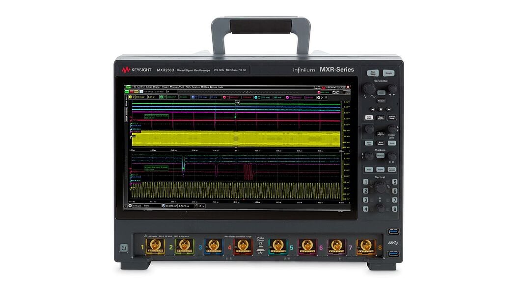
- Oscilloscopes: Essential for measuring switching times, distortion, and transient behaviors. Consider portable models for fieldwork or high-bandwidth units for RF applications.
- Signal analyzers: Ideal for examining noise performance and frequency response. Spectrum analyzers are particularly useful for RF transistor work.
- Signal generators: Provide controlled test signals to verify circuit response and switching thresholds.
- Passive components: Capacitors and resistors remain critical in biasing and stabilization networks. Keep a variety of precision-rated components for experimentation.
Further learning paths:
- Advanced tutorials and guides, such as the Electronics Tutorials Bipolar Transistor page, explain concepts step by step.
- Books such as The Art of Electronics by Horowitz and Hill or Semiconductor Device Fundamentals by Pierret offer in-depth exploration.
- Online courses and video lectures provide interactive explanations of advanced biasing, switching losses, and device modeling.
Engineering communities and forums:
- EEVblog Forum and All About Circuits host active discussions where you can troubleshoot with peers.
- IEEE membership communities provide access to peer-reviewed resources and technical conferences.
- Reddit’s r/Electronics offers quick insights and practical advice, though always verify details against authoritative sources.
By combining high-quality tools, structured resources, and community support, you can stay current with evolving transistor technologies and apply them more effectively in your projects.
Conclusion
Transistors may be small in size, but they shape the foundation of nearly every electronic design. In this guide, we’ve explored how they work at the physical and circuit level, clarified common challenges, and highlighted advanced techniques that give you more control over performance and reliability.
The real progress comes when you take this knowledge into the lab. Applying the principles covered here builds engineering intuition that no datasheet alone can provide. Each successful test strengthens your ability to design circuits that are efficient, robust, and scalable.
Engineers who master transistor behavior also position themselves to adapt quickly as technologies evolve, whether that’s wide-bandgap devices in power electronics or nanoscale transistors in advanced processors. Staying ahead requires not just understanding the theory, but also having the right tools to validate and refine designs in practice.
At Keysight, we help you achieve that with Premium Used Equipment. Our certified, like-new instruments backed by warranty, calibration, and expert support give you the confidence of OEM quality at significant savings. It’s a way to get the precision and reliability you need for transistor testing and circuit validation, without waiting months for new equipment. Explore Keysight’s Premium Used options to strengthen your design process today.
Whenever You’re Ready, Here Are
5 Ways We Can Help You
Call tech support US: +1 800 829-4444
Press #, then 2. Hours: 7am – 5pm MT, Mon– Fri
Contact our sales support team
Create an account to get price alerts and access to exclusive waitlists
Talk to your account manager about your specific needs.
Frequently Asked Questions
How can I identify if a transistor is faulty in my circuit?
Start by measuring voltage drops and monitoring electric current across terminals with a multimeter or oscilloscope. A faulty device may show no conduction when biased correctly, abnormal leakage, or a short circuit between terminals. Comparing performance to a known good device is often the quickest check.
What are the key differences between BJT and MOSFET operation in practical use?
BJTs are current-driven and perform well in linear amplification, while MOSFET transistors rely on the field effect, where a gate voltage controls conduction without significant gate current. This difference makes the Field-Effect Transistor family ideal for fast switching in efficiency-critical applications.
How do temperature variations affect transistor reliability and performance?
Rising temperatures increase leakage and alter device characteristics. In power transistors, excessive heat can trigger thermal runaway. Good thermal design — including heatsinks, airflow, and proper derating — ensures stable operation under varying conditions.
What are the best practices for selecting a transistor for high-frequency circuits?
Look for high transition frequency (fT) and low capacitance devices. MOSFET transistors and wide-bandgap devices like GaN or SiC excel at fast switching. For RF circuits, PCB layout must minimize parasitics to preserve stability.
How do I interpret transistor datasheets to choose the right device parameters?
Datasheets list maximum ratings, gain, capacitance, and switching speed. Unlike older vacuum tube devices, transistors have highly standardized specifications that enable precise design margins. This consistency is especially critical when selecting parts for microchips and large-scale integrated circuits, where billions of transistors must behave predictably.
What tools and techniques are recommended for measuring transistor behavior in circuits?
Oscilloscopes reveal voltage waveforms, spectrum analyzers measure noise, and curve tracers map I-V relationships. In complex integrated circuits, advanced tools such as source measure units (SMUs) provide detailed transistor-level data.
How can I troubleshoot common transistor circuit failures step-by-step?
Verify bias voltages, confirm expected input and output signals, and check for heat buildup. If the transistor fails, replace it with a component of equal or higher rating to isolate the issue. Careful measurement at each stage helps identify the exact point of failure.
What are typical failure modes of transistors under power stress?
Failures include junction breakdown, leakage growth, and catastrophic shorts. Power transistors in switching applications are particularly vulnerable to stress from overcurrent or insufficient cooling, leading to permanent conduction or sudden failure.
How do capacitance and ESR affect transistor circuit stability?
Parasitic capacitances and high ESR in supporting components can slow down switching or destabilize bias networks. This often causes oscillations or efficiency losses, especially in digital circuits. Using low-ESR capacitors and careful layout mitigates these issues.
Where can I find advanced tutorials or courses to deepen transistor knowledge?
Authoritative resources include The Art of Electronics, IEEE training modules, and detailed online courses. Sites like Electronics Tutorials offer step-by-step breakdowns, while engineering forums provide community-driven troubleshooting and design tips.