
Title
Decreased
Oscilloscope Glossary
What Is Resistance Measured In?
Last updated: Nov 05, 2026

Introduction
Resistance is measured in ohms (symbol Ω), the SI unit equal to one volt per ampere. In an incandescent lightbulb, electrical resistance causes the filament to heat up until it glows and produces light. This guide explains resistance units, how to measure resistance, and why impedance becomes important at higher frequencies.
When measuring resistance, even the test leads can affect your reading. The connection method you choose determines whether that extra resistance becomes part of the measurement.
Overview
- The unit: The ohm (Ω) is one volt per ampere. Ohm's law links the three quantities: V = IR.
- The scale: Resistance values range from micro-ohms to gigaohms, covering applications from busbar connections to cable insulation.
- The instruments: A multimeter measures resistance directly, while a micro-ohm meter is designed for very low resistance measurements.
- The limit: Resistance alone does not describe how a component behaves at higher frequencies. Impedance includes both resistance and reactance and can be measured using a network analyzer or impedance analyzer. The Keysight E5071C, available used, supports measurements up to 20 GHz with options 2K5 or 4K5. Its data sheet lists May 31, 2021, as the last order date, and Keysight recommends the E5080B for new purchases.
What Is Electrical Resistance?
Resistance is an object's opposition to the flow of electric current. In metal conductors, resistance results from interactions between moving electrons and the material's atoms. For a given voltage, a higher resistance means a lower current.
Resistance and Ohm's Law
Ohm's law is named after the German physicist Georg Simon Ohm, who published it in 1827. It describes the relationship between resistance, voltage (electrical potential difference), and current. The law can be written in 3 ways:
- Voltage equals current times resistance (V = IR)
- Current equals voltage divided by resistance (I = V/R)
- Resistance equals voltage divided by current (R = V/I)
The reciprocal of resistance is conductance, G = 1/R, measured in siemens (S); see the conductance formula. For a quick calculation, use the Ohm's law calculator, or read the longer explanation in What Is Ohm's Law?.
Key Takeaway
Resistance limits current. A multimeter measures it directly, while in AC and RF circuits, resistance is the real component of impedance.
What Is Resistance Measured In? The Ohm
Named after Georg Ohm, the ohm (Ω) is the standard unit of electrical resistance. A 10 V supply across a 5 Ω resistor drives 2 A, because I = V/R = 10 V / 5 Ω, consistent with the National Institute of Standards and Technology (NIST) definition of one ohm as one volt per ampere.
Sub-Units and Multiples of the Ohm
Resistance spans a wide range, so engineers use SI prefixes such as:
- Micro-ohm (µΩ) = 1/1,000,000 of an ohm
- Milliohm (mΩ) = 1/1,000 of an ohm
- Kiloohm (kΩ) = 1,000 ohms
- Megohm (MΩ) = 1,000,000 ohms
- Gigaohm (GΩ) = 1,000,000,000 ohms
A 4.7 kΩ resistor is 4,700 Ω. Connector contact resistance is usually quoted in milliohms, and cable insulation resistance in megohms or gigaohms.
How Is Resistance Measured?
The usual tool is the ohmmeter, which is built into most multimeters. A multimeter handles most everyday resistance measurements. For specialized applications, the guide to instruments for measuring resistance compares multimeters with bridges, LCR meters and micro-ohm meters. For the steps on a single part, see how to test a resistor with a multimeter.
How Does an Ohmmeter Work?
A digital multimeter sends a small, known test current through the part and measures the voltage across it. It then applies Ohm's law, R = V/I, to display the resistance. Keysight's technical support article on resistance measurement explains that the test current can heat the component and affect its resistance. This is particularly important for temperature-sensitive components, as Keysight's DMM guidance notes. Switch off the circuit, discharge any capacitors and, where you can, disconnect the part before measuring, as Keysight's guide to testing a resistor advises.
The connection method also affects measurement accuracy. Two common approaches are:
- Two-wire: The same pair of leads carries the current and senses the voltage, so the lead resistance is included in the reading. That suits resistances well above the leads' own.
- Four-wire (Kelvin): One pair of leads carries the test current, while a separate pair measures the voltage directly across the component, minimizing errors caused by lead resistance. Keysight's resistor-testing guide says it removes lead-wire resistance errors, which matters most for low-value resistors.
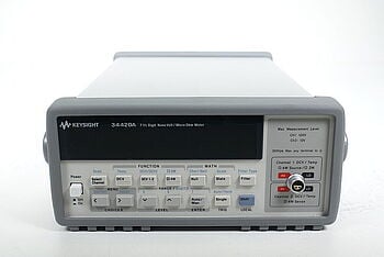
For very low resistance values, a dedicated instrument can help. According to its data sheet, the Keysight 34420A, pictured above, offers resistance sensitivity down to 100 nΩ and supports both 2-wire and 4-wire measurements.
Can an Oscilloscope Measure Resistance?
Oscilloscopes display how electrical signals change over time. They measure voltage rather than resistance directly. With a current probe, or a shunt resistor of known value, they can show current as well. For a component behaving as a pure resistance, dividing the voltage across it by the current through it gives its resistance, provided the current is not zero. This can help you observe resistance changes during operation, such as when a thermistor heats up. For a single fixed part, a multimeter is simpler.
How Does Resistance Affect Signal Integrity?
Resistance affects signal quality in high-speed digital circuits by contributing to signal loss as current travels through conductors. At radio frequencies, the skin effect causes current to concentrate near the surface of a conductor, as explained by HyperPhysics. Attenuation, the drop in signal amplitude along a wire or line, reduces the signal that reaches the receiver. Along with the effects of capacitance and inductance, resistance contributes to a signal path's impedance. Proper impedance matching helps reduce signal reflections.
Where Does Resistance Become Impedance?
In an ideal DC circuit, resistance describes the opposition to current. In AC and RF circuits, impedance includes both resistance and reactance, which comes from inductance and capacitance. Impedance (Z = R + jX) is also measured in ohms. A physical resistor also has small amounts of parasitic inductance and capacitance, so its impedance can differ from its DC resistance as frequency increases.
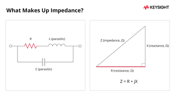
A network analyzer measures reflection (S11) across a frequency sweep and can calculate impedance from those measurements. An LCR meter can also measure impedance, typically at lower frequencies. For more detail, see how to measure impedance for measurement methods and instruments, or the impedance formula guide for the calculations.
Why Does Understanding Resistance Matter?
The table shows how resistance affects current and power dissipation under different conditions:
| Factor | High Resistance | Low Resistance |
|---|---|---|
| Current Flow | Decreased | Increased |
| Power Dissipated (same voltage) | Decreased | Increased |
| Power Dissipated (same current) | Increased | Decreased |
Factor
High Resistance
Low Resistance
Current Flow
Title
Increased
Increased
Power Dissipated (same voltage)
Title
Decreased
Decreased
Title
Increased
Increased
Power Dissipated (same current)
Title
Increased
Increased
Title
Decreased
Decreased
The power comparisons differ because one assumes constant voltage and the other assumes constant current. At a fixed voltage, a lower resistance results in greater power dissipation. At a fixed current, a higher resistance results in greater power dissipation.