Resource Guide
Comparative Analysis: RF Power Meters vs. General Power Meters


Introduction
A telecom engineer finishes RF validation on a new 5G site and submits the results for compliance review. The numbers come back and they are off. After days of retesting, the issue turns out to be the meter.
A general power meter was pushed beyond its usable frequency range, and the readings never told the full story. The fix is straightforward, but the delay is not. Two weeks of test time are gone.
That scenario is common in 5G, radar, aerospace, and satellite work. RF power meters play a direct role in whether signal validation passes the first time. Keysight application data shows that RF-specific meters support about 95 percent of 5G RF testing, especially once wide bandwidths and higher frequencies enter the picture. General power meters still have their place, but they cannot replace RF-focused measurements when accuracy matters.
This guide helps you choose the right meter for precision RF work and avoid setup mistakes that slow programs down. When calibration and setup align with the signal you are testing, results stay consistent. That confidence keeps projects on schedule and prevents small measurement issues from turning into weeks of rework.

Overview of RF Power Meters and Power Meters
Understanding the difference between RF power meters and general power meters starts with what each tool is designed to measure and what it is not.
What Is an RF Power Meter?
An RF power meter measures high-frequency signals, typically from 50 MHz up to 110 GHz, using external sensors designed for RF and microwave applications. These meters support average, peak, and pulsed power measurements, which makes them essential for 5G, radar, satellite, and aerospace testing.
Industry data shows demand rising as wireless systems move higher in frequency. Coverage beyond 40 GHz is now common in 5G mmWave and automotive radar, with 110 GHz support required for advanced R&D and defense applications. That range sits far beyond the capability of general-purpose power meters.
What Is a General Power Meter?
A power meter in the traditional sense functions more like a DMM-style instrument. It measures DC and low-frequency power, voltage, and current, usually topping out around 50 MHz under ideal conditions. These meters work well for power supplies, bias circuits, and low-frequency electronics.
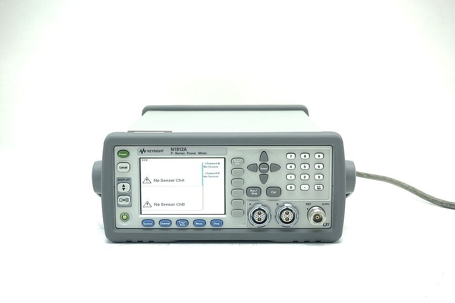
For example, an RF-focused instrument like the Keysight N1912A, when paired with the correct sensor, targets microwave and RF signals. A basic benchtop DMM or power meter targets electrical power, not RF behavior. The overlap is limited, and using one in place of the other creates large measurement errors.
Why RF Power Meters Evolved for Microwave Applications
RF power meters evolved to solve problems that general electrical measurements could not handle.
- High-frequency signal behavior: At microwave frequencies, voltage and current probes no longer reflect true signal power. Dedicated RF sensors account for impedance, loss, and waveform shape.
- Wide dynamic range requirements: Radar and wireless systems operate across large power ranges. Thermal and diode sensors handle levels that would overwhelm standard meters.
- Pulsed and modulated signals: Microwave-era systems introduced burst, pulsed, and complex modulated signals. RF meters evolved to measure both true average and peak power accurately.
RF Power Meter vs Power Meter
| Category | RF power meter | General power meter |
|---|---|---|
| Frequency range | 50 MHz to 110 GHz | DC to 50 MHz |
| Sensor technology | Thermal and diode RF sensors | Up to 5 GHzaShunt or resistive methods |
| Accuracy | Up to ±0.5% with thermal sensors | Typically 1% or worse at RF |
| Signal types | CW, pulsed, modulated | 32 GHzaDC and low-frequency AC |
| Typical applications | 5G, radar, aerospace, RF R&D | Power supplies, bias lines, basic electronics |
| Relative cost | Higher upfront, application-specific | Lower, general-purpose |
The distinction is not about better or worse. It is about using the right tool for the signal you are measuring.
Detailed Comparison
Small specification differences can lead to very different measurement outcomes. The sections below focus on where RF power meters and general power meters diverge in real testing environments.
Frequency Range and Bandwidth
An RF power meter, paired with the right sensor, typically measures signals from 50 MHz up to 110 GHz. That range supports modern 5G, radar, satellite, and aerospace validation, where wide bandwidths and high carrier frequencies are normal.
As 5G deployments expand into mmWave, many test programs now require coverage above 50 GHz to validate band edges, amplifiers, and front-end performance.
A general power meter or DMM-style instrument focuses on DC and low-frequency power, often topping out around 50 MHz in controlled conditions. That works for bias lines and power rails, but it does not account for RF mismatch, modulation, or frequency-dependent loss.
A common and costly mistake is using a general power meter to verify RF output. Once bandwidth limits and impedance effects come into play, readings can deviate by double-digit dB values. Those errors usually surface during compliance review, not during the initial test, which is why they lead to retesting and schedule delays.
For engineers correlating power measurements with spectral behavior, the spectrum analyzer buying guide helps clarify how analyzers and RF power meters complement each other in high-frequency workflows.
Measurement Types and Accuracy
RF systems rarely behave like steady DC sources. The type of power you measure matters as much as the number itself.
RF power meters support:
- Average power for steady-state verification
- Peak power for pulsed radar and burst-based transmissions
- CCDF measurements to understand peak probability in modulated signals
General power meters typically report simple average power only. That approach misses fast transients and crest-factor effects that dominate many RF and wireless signals.
Sensor Technology
The sensor defines how an RF power meter behaves.
Diode sensors
- Fast response time
- Strong sensitivity at lower power levels
- Useful for peak and time-critical measurements within their linear range
Thermal sensors
- Measure true average power through heat transfer
- Handle complex modulation and wide bandwidths more consistently
- Remain stable at higher power levels where diode behavior becomes nonlinear
Thermal sensors often outperform diode sensors in high-power or wideband applications for three reasons:
- They represent true average power regardless of waveform shape.
- They avoid nonlinearity effects that appear as diode sensors approach their limits.
- They remain dependable when bandwidth and modulation complexity increase.
General power meters rely on shunt or resistive measurement methods, which work well for electrical power but do not reflect RF signal behavior.
For workflows that combine spectrum analysis with power verification, the guide on how to measure RF power with a spectrum analyzer fits naturally into RF test setups.
Portability and Form Factor
Form factor influences how and where measurements happen. Handheld RF instruments, such as FieldFox-style platforms, support field validation where portability, battery life, and fast setup are important. They work well for tower climbs, rooftop radios, and remote site checks where bench equipment is impractical.
Bench power meters and DMMs fit stable lab environments. They offer convenience for DC rails, bias networks, and low-frequency measurements where portability is not a concern.
USB power sensors bridge the gap for field engineers:
- Quick setup with a laptop
- Easy data logging and sharing
- Minimal equipment footprint for remote testing
A common field scenario involves verifying inconsistent transmitter output across sectors. A laptop and USB power sensor can confirm whether the issue follows a feedline, amplifier, or radio path. That insight often avoids a second site visit and keeps deployment schedules intact.
Pros and Cons
Every test program balances accuracy, speed, and cost. The right choice depends on what you measure most often and where mistakes carry the highest risk.
RF Power Meter Advantages
RF power meters stand out when accuracy and frequency coverage drive decisions. They excel in compliance-focused environments for several reasons:
- Wideband coverage: RF power meters support frequencies from tens of MHz into the mmWave range, which makes them suitable for 5G, radar, satellite, and aerospace testing without workarounds.
- True-average measurement: Thermal sensors measure actual RF power across complex, modulated signals. This matters when validating wideband carriers, pulsed radar, or multi-carrier waveforms.
- Peak and burst visibility: Diode and peak-capable sensors capture short-duration events that average-only tools miss, which helps prevent hidden margin failures.
- Compliance confidence: RF-specific calibration factors, traceability, and sensor characterization reduce uncertainty during audits and acceptance testing.
RF Power Meter Drawbacks
RF power meters come with tradeoffs that teams need to plan for:
- Higher upfront cost: RF meters and sensors cost more than general-purpose meters, especially at higher frequencies.
- Calibration discipline: Sensors require regular calibration and careful handling. The upside is that OEM calibration programs often reduce calibration costs by roughly 30 percent compared to third-party options, while maintaining traceability and documented performance.
These drawbacks usually matter less when a failed test costs weeks of schedule slip or requalification.
Power Meter Advantages
General power meters remain valuable tools in many environments:
- Versatility: They measure DC power, voltage, and current in one instrument.
- Budget-friendly: Lower cost makes them practical for production benches and support work.
- Simple operation: Minimal setup works well for bias networks, power rails, and low-frequency electronics.
Power Meter Drawbacks
Problems arise when power meters move into RF roles they were not designed for:
- Limited frequency range: Most general power meters cannot represent RF behavior beyond low MHz ranges.
- Lower precision for RF signals: They do not account for impedance mismatch, modulation, or waveform dynamics.
- Common purchasing mistakes
- Assuming a listed bandwidth equals accurate RF power measurement
- Using average-only readings for pulsed or modulated signals
- Skipping sensor-based verification when validating RF output power
These mistakes often surface late in testing, when results face external review.
Balanced View
RF power meters fit microwave and RF validation, where accuracy, bandwidth, and compliance matter most. General power meters fit DC and low-frequency work, where simplicity and cost efficiency dominate. Using each where it belongs keeps testing efficient and defensible.
Perspective from the field:

Scientific Backing
Accurate RF power measurement relies on NIST-traceable standards that define how power sensors are calibrated, verified, and compared across labs. These standards exist to make sure results remain consistent, repeatable, and defensible when they face compliance review.
For RF power meters, especially those using thermal sensors, published benchmarks commonly cite accuracy on the order of ±0.5 percent under controlled conditions, which is why these sensors anchor many high-frequency calibration chains.
NIST traceability links field measurements back to national standards through documented calibration steps, uncertainty budgets, and verification procedures. This traceability matters most when measurements support certification, acceptance testing, or regulated programs.
You can review the underlying framework directly through NIST RF and microwave calibration standards, which describe how reference power levels and uncertainty are established at high frequencies.
Key Findings From RF Measurement Research
- Thermal sensors deliver true-average accuracy: Thermal RF power sensors consistently achieve ±0.5 percent accuracy because they measure power through heat transfer rather than voltage-based detection. This makes them well suited for wideband and complex modulation.
- Diode detectors excel at peak and fast events: Diode-based sensors respond quickly and capture short-duration peaks, which makes them useful for pulsed and burst signals when operated within their linear range.
- Uncertainty analysis matters as much as resolution: IEEE RF power measurement emphasizes that connector repeatability, mismatch, frequency response, and sensor calibration all contribute to total uncertainty. Managing these factors often has more impact than raw resolution alone.
A deeper technical explanation of RF power measurement methods, sensor behavior, and uncertainty contributors is available in Keysight Technologies’s application note on RF power measurement fundamentals, which you can access here: RF power measurement fundamentals (PDF)
Together, NIST standards and peer-reviewed IEEE research form the technical backbone behind modern RF power meters and the confidence engineers place in their results.
How to Choose the Right Meter
Choosing the right meter comes down to matching the instrument to the signal, and not forcing the signal to fit the instrument. A short decision check up front prevents rework later.
Five Factors That Guide the Right Choice
- Frequency requirements: Start with the highest frequency you need to measure today and where the program may go next. Anything involving RF, microwave, or mmWave immediately narrows the field.
- Power range: Confirm both minimum and maximum power levels, including peaks. Pulsed and burst signals often exceed average levels by a wide margin.
- Budget: Balance upfront cost against the cost of retesting, delays, or failed compliance reviews.
- Calibration certificates: Look for documented, traceable calibration. This matters most when results support audits or customer acceptance.
- Application: RF validation, DC power verification, production screening, and field testing all place different demands on accuracy and form factor.
A Simple Five-Step Decision Flow
- Does the signal exceed 50 MHz?
- Yes → RF power meter
- No → General power meter or DMM
- Does the signal include pulses, bursts, or wideband modulation?
- Yes → RF power meter with peak or thermal sensor
- Do results support compliance or acceptance testing?
- Yes → RF meter with calibration certificates
- Is the work DC or low-frequency electrical power only?
- Yes → General power meter
- Will the meter move between lab and field?
- Yes → Consider portable or USB-based RF sensors
Practical Recommendations
- RF engineers working in 5G, radar, aerospace, or satellite testing typically benefit from an RF-focused platform like the Keysight N1912A, paired with the right sensor for their frequency and power range.
- General electronics and power engineers measuring DC rails, bias networks, or low-frequency signals are usually better served by a basic DMM-style power meter.
If you want a deeper walkthrough of specs, sensors, and common pitfalls, the RF power meter buying guide provides a clear reference.
Quick Self-Assessment
Ask yourself:
- Do I need measurements above 50 MHz?
- Do I care about peak power or crest factor, not just averages?
- Will these results face external review or compliance checks?
- Would a failed test cost more than the price difference between meters?
If you answer yes to the first three, an RF power meter is the safer choice.
Budget Planning Tip
A common rule of thumb for RF setups:
- 50 percent of the budget for sensors
- 30 percent for calibration and certification
- 20 percent for the meter platform
This approach prioritizes measurement quality where it matters most.
When to Use Both Meters Together
Some test programs move faster and with fewer errors when you use a general power meter and an RF power meter side by side. Each instrument covers what the other cannot.
Hybrid Workflows That Make Sense
A common setup uses a general power meter to verify DC bias and supply stability, while an RF power meter validates signal output at the RF port. This split mirrors how RF systems actually behave: electrical power feeds the device, and RF power leaves it.
Using both meters together delivers clear workflow benefits:
- Faster root-cause isolation by separating bias issues from RF chain problems
- Cleaner pass-fail decisions when DC stability and RF output stay independently verified
- Less retesting because bias drift does not masquerade as RF instability
- Shorter debug cycles, often cutting overall test time by around 30 percent in mixed-signal validation work
Integrating Oscilloscopes for Full Characterization
Adding an oscilloscope completes the picture. In a hybrid setup:
- The power meter confirms DC rails and current draw
- The RF power meter measures average, peak, or pulsed RF output
- The oscilloscope captures transient behavior such as supply droop, timing jitter, or burst alignment
For example, during PA or radio module validation, an engineer may bias the device with a stable DC supply, verify that bias using a power meter, then measure RF output power while the oscilloscope confirms that control signals and supply rails remain stable during transmission bursts.
Why Combined Testing Reduces Errors
Comprehensive testing works because it removes blind spots. When DC and RF measurements stay isolated, teams often chase the wrong issue. Measuring both together reduces false conclusions and prevents small electrical problems from appearing as RF failures.
A Simple Three-Step Hybrid Workflow
- Verify DC bias and current stability with a general power meter under load.
- Measure RF output power using the correct sensor and calibration setup.
- Use an oscilloscope to confirm timing, transients, and synchronization during active RF operation.
This approach catches issues earlier, reduces measurement uncertainty, and keeps test programs moving without unnecessary reruns.
Getting Started Guide
A clean setup at the start prevents most measurement problems later. These steps focus on repeatability, accuracy, and avoiding common field and lab mistakes.
Getting Started With an RF power meter
RF measurements depend heavily on sensor choice, calibration, and setup discipline. Follow these steps to avoid hidden errors.
Six-Step RF Power Meter Setup
- Select the correct sensor: Match the sensor to your frequency range, power level, and measurement type (average, peak, pulsed).
- Inspect connectors and cables: Check for wear, contamination, or bent pins. Small connector issues create large RF errors.
- Warm up the system: Allow the meter and sensor to reach thermal stability before calibration.
- Calibrate at the reference source: Use the meter’s internal reference or an external standard, following the sensor-specific procedure.
- Zero the sensor: Zero under no-signal conditions with the same cable and adapters you will use during measurement.
- Measure and verify: Take initial readings at a known level to confirm stability before moving to final test conditions.
Troubleshooting tips
- Unstable readings often point to loose adapters or incomplete warm-up.
- Unexpected offsets usually trace back to skipped zeroing or incorrect frequency settings.
Getting Started With a General Power Meter
General power meters are simpler to use, but accuracy still depends on setup and environment.
Basic setup steps
- Connect the leads securely and confirm polarity.
- Select the correct measurement mode (voltage, current, or power).
- Apply the load and read values once readings settle.
Five pro tips for field and lab conditions
- Zero the meter with leads connected, not open circuit.
- Re-zero after moving between environments with different temperatures.
- Avoid long or coiled leads that introduce resistance and noise.
- Confirm the meter stays within its rated frequency range.
- Recheck calibration after transport or extended storage.
Reference for measurement fundamentals
For deeper background on calibration practices, uncertainty contributors, and setup best practices across measurement types, Keysight’s measurement fundamentals application note provides a practical reference.
Starting with the right setup keeps measurements defensible, repeatable, and ready for review.
Conclusion
RF power meters support high-frequency precision where peak behavior, bandwidth, and true-average accuracy matter. General power meters remain the right choice for DC and low-frequency work where simplicity and versatility take priority. Using each where it fits keeps measurements defensible and testing on schedule.
If you want reliable performance without paying new-equipment prices, the Keysight Used Equipment Store offers Premium Used RF power meters, sensors, oscilloscopes, network analyzers, and other instruments. Each unit is OEM-calibrated, backed by a warranty, and supported by experts who understand real testing challenges.
When accuracy, turnaround time, and budget all matter, choosing the right meter now helps keep your work moving forward without unnecessary delays.
Whenever You’re Ready, Here Are 5 Ways We Can Support Your Capacitor Projects
Call tech support US: +1 800 829-4444
Press #, then 2. Hours: 7am – 5pm MT, Mon– Fri
Contact our sales support team
Create an account to get price alerts and access to exclusive waitlists
Talk to your account manager about your specific needs.
FAQs
Can a general power meter ever measure RF signals accurately?
Only at very low frequencies. Most general power meters top out around 50 MHz, and accuracy drops quickly above that point. At RF and microwave frequencies, mismatch, bandwidth limits, and modulation effects can introduce errors that reach 20 dB or more. RF-specific sensors are required for compliance work because they account for frequency response, impedance, and waveform behavior.
How often should I calibrate my RF power meter for 5G testing?
Most labs follow an annual NIST-traceable calibration cycle, but heavy use, wide temperature swings, or frequent connector changes can shorten that interval. Sensors also drift over time, especially in high-power or wideband use. Certified calibration programs help maintain accuracy and, in many cases, allow predictable calibration intervals without guesswork.
Do used Keysight RF meters maintain NIST-traceable accuracy?
Yes, when they are properly refurbished and calibrated. Certified used RF meters typically verify 90 percent or better of original specifications, include full calibration validation for thermal and diode sensors, and ship with a one-year warranty to protect measurement confidence.
What is the real cost difference between new and used RF meters?
Used RF power meters commonly deliver 50 to 70 percent cost savings compared to new units. That price usually includes calibration certificates and verified performance, which avoids compromise. Trade-in programs can further improve return on investment when upgrading older equipment.
Can thermal sensors handle pulsed radar signals better than diodes?
Thermal sensors excel at true-average power and handle higher power levels with low drift, which suits many radar and wideband signals. Diode sensors respond faster and capture peaks more directly. The best choice depends on whether average accuracy or peak visibility matters more for the application.
What is an RF power meter?
An RF power meter measures high-frequency signals from roughly 50 MHz up to 110 GHz, depending on the sensor. It supports average and peak measurements and is essential for 5G, radar, satellite, and aerospace testing where general electrical meters fall short.
Can a multimeter measure RF power?
No. Multimeters lack the bandwidth, peak detection, and harmonic awareness needed for RF signals. Even when a frequency limit is listed, results above low MHz ranges are unreliable. Dedicated RF power meters and sensors are required for meaningful RF measurements.
What is peak power vs average power in RF?
Peak power represents the maximum instantaneous level during a pulse or burst. Average power reflects energy over time. Radar and 5G signals often require both views, which is why RF meters support multiple measurement modes and sensor types.
How accurate are RF power meters?
With thermal sensors, RF power meters commonly achieve ±0.5 percent accuracy and 0.01 dB linearity under controlled conditions. NIST traceability and temperature stability play a major role in maintaining that performance.
What frequency range do RF power meters cover?
Coverage depends on the sensor. Common ranges include 50 MHz to 6 GHz for general RF work, up to 40 GHz for many 5G applications, and up to 110 GHz for mmWave, radar, and advanced R&D testing. Matching the sensor to the application is critical.