
Detect different wire bond deformation defects with VTEP
There are different types of wire deformations defects in an IC. Using electrical test methods, automated test equipment (ATE) can capture some of the defect types while others require different test methods. In my previous post on IC wire bond deformation detection depends on its package type, we discussed the VTEP measurement methodology on the wire bonds, and how it is able to detect wire bond defects on different packaging design.
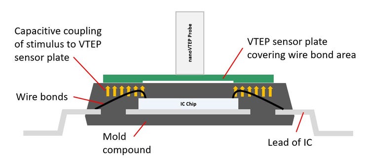
During the measurement, the VTEP sensor plate on the top of the IC picks up the capacitive coupling response from the wire bonds. The level of the capacitive coupling depends on the strength of the stimulus at the wire bond, and the distance between the wire bond to the sensor plate above. The distance between the wire bond and the sensor plate determines how much capacitive coupling can take place.
Wire bond deformation defects covered by Automated Test Equipment (ATE)\

Shorted, opened, and missing wire defect types are detectable with ATE systems as these are electrical defects. However, these defects manifest themselves differently with VTEP test. A missing wire defect results in very low measurement as there is no wire for coupling to happen. On the other hand, a shorted wire gives significantly higher measurement due to an increase in the surface area for coupling. As for open wire defects, it depends on where the disconnection of the wire bond occurs. VTEP may not be able to cover all kinds of open defects. \
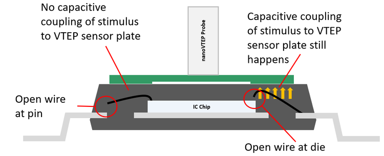
When the open occurs at the pin end of the wire bond, the stimulus will not be able to reach the wire bond itself. As such, minimum coupling will take place with the sensor plate. An open defect located at the die end allows stimulus to make its way up onto the wire bond. The stimulus couples with the sensor plate and results in a false pass call. Fortunately, all three of the above-mentioned defects are detectable using ATE test systems.
Wire bond deformation defects not covered by automated test equipment (ATE)

Extra/stray wire, near short sagging wire, and near short sweeping wire defects are challenging, since they are not detectable by any ATE test system as they are non-electrical defects. Being non-electrical, the IC appears to be fully functional during ATE tests, but the insulation around the defective wires degrades over time and eventually fail.
Extra/stray wire, near short sagging wire, and near short sweeping wire defects are challenging, since they are not detectable by any ATE test system as they are non-electrical defects. Being non-electrical, the IC appears to be fully functional during ATE tests, but the insulation around the defective wires degrades over time and eventually fail.
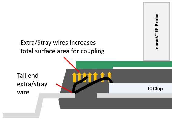
Extra/stray wires can occur from improper termination of the wire bond. These extra lengths of wire become active with the stimulus during testing and add on to the overall capacitive coupling to the sensor plate. The wire may also overlap adjacent wires and affect their measurement as well. Depending on the actual position and length of the wire, you get different fluctuations in the VTEP measurements.
Near short sagging wire is easily detectable with VTEP as it presents itself as a large fluctuation in measurement. The term “sagging” implies that the deformation of the wire is always downwards. In fact, the defect can either be downwards or upwards.\
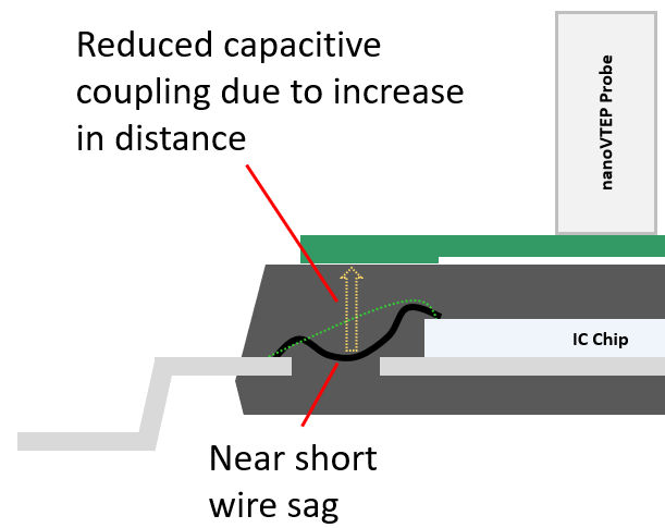
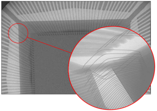
Regardless of which direction the deformation goes, what is important is that the deformation creates a change in the vertical distance between the wire and the VTEP sensor plate above. The significant change in the capacitive coupling strength makes it easy to detect.
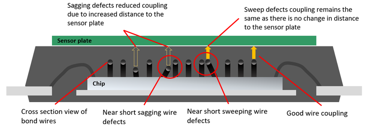
In real life, deformation can happen in any direction: vertically, diagonally, or horizontally. When the deformation is almost horizontal, it becomes a near short wire sweep defect. Such a defect may be difficult for VTEP to pick up as there is no significant change in the vertical axis to have any impact on the capacitive coupling strength. The drift in measurement becomes minimal and may not be large enough to indict a failure.
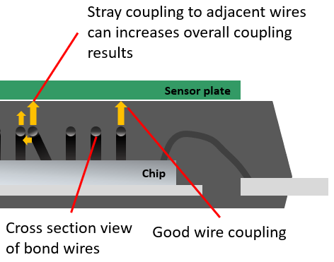
However, capacitive coupling can happen in all directions. When the sweeping wire gets close to the adjacent wire, the stimulus can couple over to the adjacent wire, adding to the overall surface area to increase the capacitive coupling strength. The larger surface area for coupling may or may not be sufficient to result in a failure though. This makes the detection of near short sweeping wires challenging.
Until the next post, stay healthy and safe!
Ping me up with your questions or comments !
kwan-wee_[email protected]