Testing the higher, dynamically variable power provided by the USB Type-C power delivery (PD) system requires extensive verification and testing to achieve compliance with USB Type-C standards. End-to-end USB Type-C connections between devices are made through configuration channel (CC) lines. Cable orientation — a critical factor for Type-C connectors — is also determined through the CC line. During compliance testing, important design parameters for PD that must be measured include: voltage level, device charging, cable functionality, and determination of provider versus consumer device status.
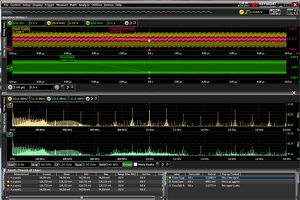
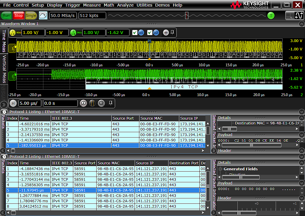
When a Type-C consumer device requests a specific power profile, verification that the connected provider sourced the right voltage, current, or wattage profile is needed. The CC lines CC1 / CC2 are monitored with a 300 kHz signal and measured for proper protocol, generated voltage, and current. The resulting eye diagram is analyzed with an oscilloscope. Verifying the PD circuit layout requires performing power integrity measurements of key parameters like supply drift, periodic and random disturbances (PARD), programmable power rail response, and high-frequency transient and noise.
USB Type-C power delivery test solution
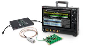
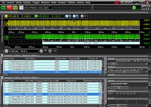
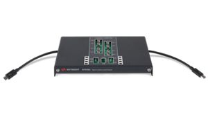
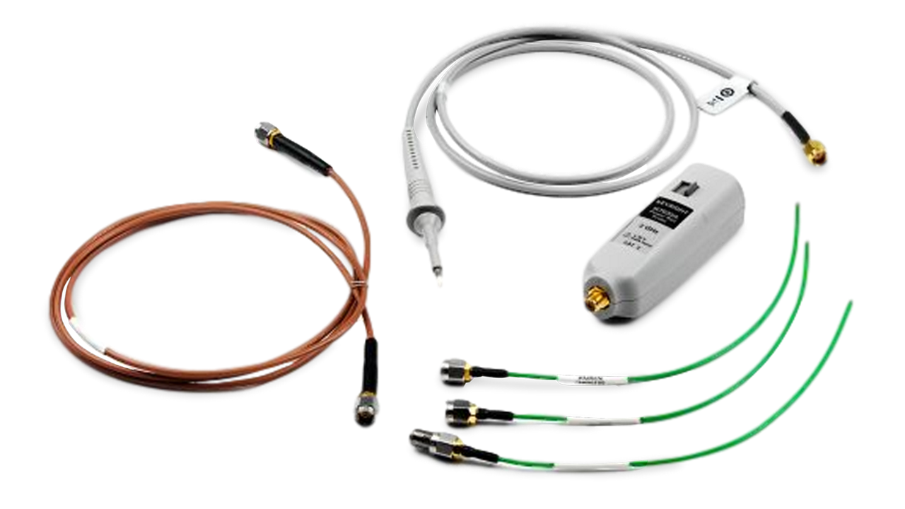
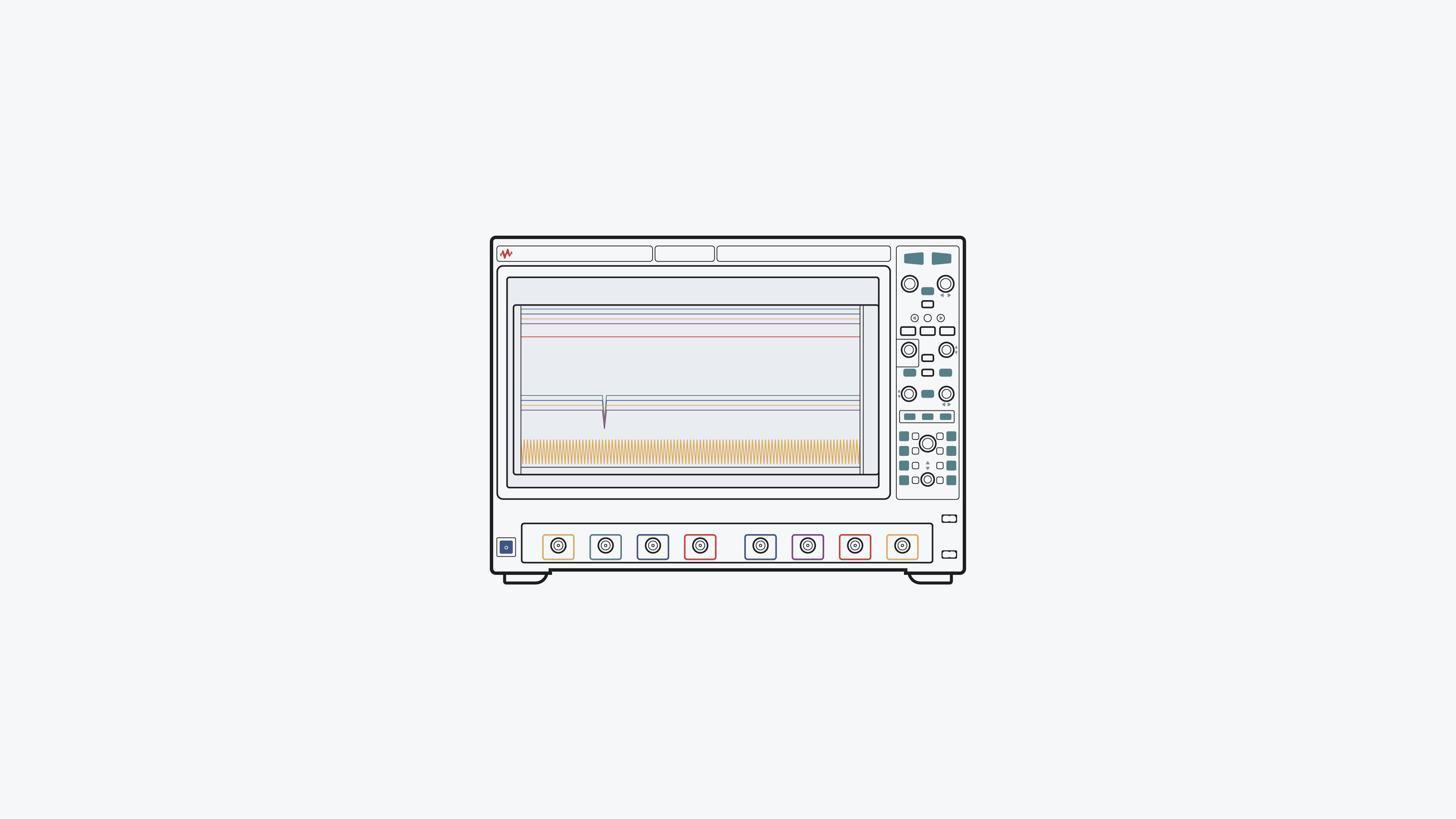
Testing USB Type-C power delivery components requires monitoring the CC line for proper protocol and measuring the generated voltage and current. The Keysight USB Type-C power delivery test solution, comprising a 500 MHz MXR-Series Infiniium oscilloscope with D9010EMBP embedded protocol software and N7019A Type-C breakout provides real-time protocol triggering and debugging of Type-C CC biphase mark encoded 300 kbps signals. This process includes advanced USB triggering, time-correlated decode trace, protocol lister / tabular window view, and a USB power delivery search capability. D9010ASIA crosstalk analysis software and D9010POWA power integrity analysis software help provide further power integrity measurement capabilities.
Use the N7019A to access all your Type-C signals in a live link. The acquired signals can be used for debug or decoded with USB-PD, USB 2.0, USB 3.2, or USB4 Protocol Decode Software.