


Title
Interference a device puts onto power lines and cables
Oscilloscope Glossary
What Is EMI Testing?

Introduction
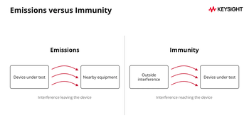
EMI testing measures the electromagnetic interference (EMI) a device emits and checks it against the limit a standard sets. Immunity testing checks whether the device continues working when exposed to outside interference. Together, emissions and immunity testing are the 2 main parts of electromagnetic compatibility (EMC) testing. A product can pass its functional tests and still fail EMI testing.
Although oscilloscopes are rarely used for formal emissions compliance measurements, they still have an important role in troubleshooting EMI problems. We'll explain when to use one and how it fits into the testing process.
Overview
- Emissions and immunity testing: Both are important for electromagnetic compatibility (EMC). Emissions testing checks interference leaving a device, while immunity testing evaluates its response to outside interference.
- Conducted tests cover interference traveling along cables and power lines. Radiated tests cover interference traveling through the air.
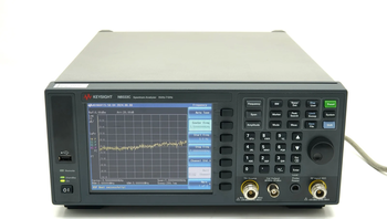
- Testing instruments include spectrum analyzers, EMI receivers such as the N9048B, oscilloscopes, and near-field probes.
- Filter checks: A network analyzer such as the E5071C (up to 20 GHz, sold used) measures a filter's insertion loss.
EMI Testing Definition
EMI testing checks whether a device's electromagnetic emissions stay within the limits set by applicable standards. As the Keysight EMI testing guide explains, electromagnetic compatibility (EMC) means equipment can operate in its intended environment without causing unacceptable interference to other devices or being adversely affected by electromagnetic disturbances.
Importance of EMI Testing
- Regulatory compliance: Many countries require products to meet EMI requirements before they can be sold. In the EU, these requirements are governed by Directive 2014/30/EU.
- Device performance: EMI can degrade how a device works, including medical and other critical devices, and testing helps you find and reduce the cause.
Types of EMI Testing
EMC testing covers both emissions and immunity, with conducted and radiated tests used for each. The table compares these 4 main test types.
| Test | What it checks | Typical setup | Typical instrument | |
|---|---|---|---|---|
| Conducted emissions | Interference a device puts onto power lines and cables | LISN between the mains and the device | Spectrum analyzer or EMI receiver | |
| Radiated emissions | Interference a device sends through the air | Antenna in a semi-anechoic chamber or on an open area test site | EMI receiver or spectrum analyzer | |
| Conducted immunity | Whether disturbances on cables upset the device | A defined disturbance injected onto cables (IEC 61000-4-6) | Test system for the chosen standard, with the device monitored | |
| Radiated immunity | Whether an external field upsets the device | Controlled test space with a transmitting antenna (IEC 61000-4-3) | RF source and power amplifier, with the device monitored |
Test
What it checks
Typical setup
Typical instrument
Conducted emissions
Title
LISN between the mains and the device
LISN between the mains and the device
Title
Spectrum analyzer or EMI receiver
Spectrum analyzer or EMI receiver
Title
Radiated emissions
Title
Interference a device sends through the air
Interference a device sends through the air
Title
Antenna in a semi-anechoic chamber or on an open area test site
Antenna in a semi-anechoic chamber or on an open area test site
Title
EMI receiver or spectrum analyzer
EMI receiver or spectrum analyzer
Title
Conducted immunity
Title
Whether disturbances on cables upset the device
Whether disturbances on cables upset the device
Title
A defined disturbance injected onto cables (<a href="https://webstore.iec.ch/en/publication/65586">IEC 61000-4-6</a>)
A defined disturbance injected onto cables (<a href="https://webstore.iec.ch/en/publication/65586">IEC 61000-4-6</a>)
Title
Test system for the chosen standard, with the device monitored
Test system for the chosen standard, with the device monitored
Title
Radiated immunity
Title
Whether an external field upsets the device
Whether an external field upsets the device
Title
Controlled test space with a transmitting antenna (<a href="https://webstore.iec.ch/en/publication/59849">IEC 61000-4-3</a>)
Controlled test space with a transmitting antenna (<a href="https://webstore.iec.ch/en/publication/59849">IEC 61000-4-3</a>)
Title
RF source and power amplifier, with the device monitored
RF source and power amplifier, with the device monitored
Title
Conducted Emissions Testing
Conducted emissions testing measures unwanted electromagnetic signals that travel from a device along its power lines, signal cables, or other conductors. Excessive emissions can disrupt other equipment on the same power circuit.
- Common applications: Products that connect to AC power, either directly or through an adapter or charger.
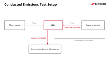
- Test setup: A line impedance stabilization network (LISN) connects the device under test (DUT) to the supply and gives the measurement a defined impedance. The LISN passes the unwanted emissions to a spectrum analyzer or EMI receiver. FCC Part 15.107, for example, sets conducted limits from 150 kHz to 30 MHz and specifies a 50 µH/50 Ω LISN. Signal and telecom ports are measured with other methods, depending on the product standard.
Radiated Emissions Testing
Radiated emissions testing evaluates the electromagnetic energy a device emits through the air. A device that radiates too much can interfere with nearby equipment, such as communication systems.
- Test setup: The DUT sits in a semi-anechoic chamber or on an open area test site (OATS). Antennas measure emissions at a set distance. FCC Part 15.109, for example, gives its main limits from 30 MHz and uses 3 meters for most unintentional radiators and 10 meters for Class A digital devices.
- Regulations: Standards such as CISPR 32 and FCC Part 15 set radiated emission limits for different product categories. CISPR 32 replaced CISPR 22 at the IEC, although FCC Part 15.109 still references CISPR 22.
Conducted Immunity Testing
Conducted immunity testing assesses whether a device can withstand electromagnetic disturbances carried on its power or signal cables. Surges and fast transients are tested separately (see Transient testing below).
- Test setup: A defined disturbance is injected into the device's power or signal lines while the device is monitored. IEC 61000-4-6 covers immunity to conducted disturbances induced by radio-frequency fields, from 150 kHz up to 80 MHz.
Radiated Immunity Testing
Radiated immunity testing evaluates how well a device resists electromagnetic fields in its operating environment.
- Test setup: The DUT is exposed to a field from a transmitting antenna in a controlled test space. The field strength is set to a test level and the frequency is swept while the device is watched for malfunctions.
- Regulations: IEC 61000-4-3 (2020 edition) establishes test levels and test procedures for immunity to radiated electromagnetic energy.
Additional Testing Types
Beyond conducted and radiated RF testing, other types of electromagnetic immunity testing may apply, depending on the device and relevant standards:
- Electrostatic discharge (ESD) testing: Tests a device against static discharges from people, directly or to nearby objects, often following IEC 61000-4-2.
- Magnetic field immunity testing: Evaluates a device's tolerance to magnetic fields at power frequencies (50 and 60 Hz), as covered by IEC 61000-4-8.
- Transient testing: Tests immunity to repetitive fast transients (IEC 61000-4-4) and to surges caused by switching and lightning (IEC 61000-4-5).
EMI Testing Standards
Regulations vary by market and reference standards that establish test methods and, where applicable, emission limits. The table lists several commonly used standards.
| Standard | Description |
|---|---|
| CISPR 11 | Industrial, scientific and medical equipment |
| CISPR 32 | Multimedia equipment (second edition, 2015). It replaced CISPR 22\. |
| CISPR 25 | Limits radio disturbances from vehicles, boats, internal combustion engines and their components, to protect on-board receivers |
| IEC 61000-4-2 | Electrostatic discharge immunity |
| IEC 61000-4-3 | Radiated, radio-frequency, electromagnetic field immunity |
Standard
Description
<a href="https://webstore.iec.ch/en/publication/66118">CISPR 11</a>
Title
Industrial, scientific and medical equipment
Industrial, scientific and medical equipment
<a href="https://webstore.iec.ch/en/publication/22046">CISPR 32</a>
Title
Multimedia equipment (second edition, 2015). It replaced CISPR 22\.
Multimedia equipment (second edition, 2015). It replaced CISPR 22\.
<a href="https://webstore.iec.ch/en/publication/64645">CISPR 25</a>
Title
Limits radio disturbances from vehicles, boats, internal combustion engines and their components, to protect on-board receivers
Limits radio disturbances from vehicles, boats, internal combustion engines and their components, to protect on-board receivers
IEC 61000-4-2
Title
Electrostatic discharge immunity
Electrostatic discharge immunity
IEC 61000-4-3
Title
Radiated, radio-frequency, electromagnetic field immunity
Radiated, radio-frequency, electromagnetic field immunity
Before planning a test, confirm which edition and regional version of each applicable standard apply to your product.
EMI Testing Equipment
Each instrument below plays a different role in finding, measuring and tracing interference.
Spectrum Analyzers
Spectrum analyzers measure signal amplitude across a range of frequencies. They help you identify and measure a DUT's emissions to determine whether further investigation is needed or whether measured levels exceed applicable limits.
- Applications: Conducted and radiated emissions testing, especially when you are troubleshooting a compliance failure.
EMI Receivers
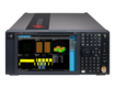
EMI receivers are designed for electromagnetic compatibility (EMC) testing. CISPR 16-1-1 specifies requirements for EMI receivers and spectrum analyzers used to measure electromagnetic disturbances from 9 kHz to 18 GHz. When an applicable product standard references CISPR 16-1-1, the measuring instrument must meet its requirements. The Keysight N9048B PXE EMI test receiver, available through the Official Keysight Used Equipment Store, covers 1 Hz to 44 GHz and is listed by Keysight as compliant with CISPR 16-1-1:2019.
- Functionality: EMI receivers typically provide peak, quasi-peak and average detectors. The Keysight EMI testing guide explains how these measurements are used in radiated emissions testing. FCC Part 15.107 specifies quasi-peak and average limits for conducted emissions.
Oscilloscopes
Oscilloscopes show voltage signals in the time domain, which makes them useful for analyzing transient EMI events. Although oscilloscopes are not typically used for formal emissions compliance measurements, they help engineers troubleshoot circuits and identify possible sources of interference.
- Use cases: Observing power supply noise and capturing transient spikes from switching or electrostatic discharge.
- Advanced capabilities: Many oscilloscopes include Fast Fourier Transform (FFT) analysis, which converts a time-domain signal into a frequency-domain view.
Near-Field Probes
Near-field probes help you locate EMI sources on a circuit board, such as noisy components or traces.
- How they work: A handheld probe picks up the magnetic or electric field close to the board and feeds the signal to an oscilloscope or spectrum analyzer.
- Advantages: Probing needs no electrical connection, so you can examine a circuit without modifying it.
- Common applications: Debugging printed circuit boards (PCBs), finding hotspots and checking shields and seams for leaks.
Steps in EMI Testing
1.
- Pre-compliance testing: Run initial tests in the design phase to find EMI problems early, when they cost less to fix.
- Selection of test environment: Use a semi-anechoic chamber or open area test site for radiated emissions, and a reference ground plane with the LISN bonded to it for conducted emissions.
- Measurement setup: Connect the DUT to the LISN for conducted emissions testing, or use an antenna to capture radiated emissions. Connect the LISN or antenna to the spectrum analyzer or EMI receiver, and keep an oscilloscope and near-field probes available for debugging. Check each instrument manual and your lab's rules before connecting mains-powered equipment.
- Data analysis: Compare the measured emission levels with the limits in the applicable standard to identify potential compliance issues and determine whether further testing or design changes are needed.
- Mitigation and retesting: Modify the design or add appropriate filtering or shielding to reduce emissions, then retest to check whether the changes were effective.
Best Practices for EMI Testing
To get accurate, repeatable results, apply these practices:
- Proper grounding and shielding: Adequate grounding and shielding can reduce both emissions and susceptibility.
- Use of filters: Add filters to suppress unwanted frequencies and reduce conducted emissions.
- Regular calibration: Calibrate your test equipment regularly to maintain measurement accuracy.
- Documentation: Keep records of test setups, procedures and results.
After adding an EMI filter, measure its performance to see how effectively it reduces unwanted signals. A vector network analyzer measures a filter's transmission coefficient (S21) across frequency, allowing you to evaluate its insertion loss in the frequency range where emissions exceeded the limits. See the Keysight glossary entry on the network analyzer for more information. The conducted range in FCC Part 15.107 starts at 150 kHz, so if you use an E5071C, pick an option that starts at 9 kHz or 100 kHz. The data sheet shows that configurations starting at 9 kHz or 100 kHz are available with upper frequency limits of up to 8.5 GHz. The 14 GHz and 20 GHz configurations start at 300 kHz, so check the installed option on each listing. The E5071C is discontinued: the data sheet gives a last order date of May 31, 2021, and Keysight recommends the E5080B for new purchases.
A standard 50 Ω sweep measures filter performance under controlled impedance conditions, typically without operating load current. Actual performance can differ because it depends on the connected circuits' impedances, operating voltage, and current. Load current can also saturate magnetic-core inductors, so use the sweep as an initial screening measurement rather than a complete assessment of filter performance. CISPR 17 gives measurement methods for filters, including S-parameters and measurements under bias.
Putting EMI Testing Into Practice
The Official Keysight Used Equipment Store offers oscilloscopes, spectrum analyzers and function generators for your EMI test bench.
Whenever You’re Ready, Here Are
5 Ways We Can Help You
1
Browse our used oscilloscopes
2
Call tech support US: +1 800 829-4444
Press #, then 2. Hours: 7am – 5pm MT, Mon– Fri
3
Contact our sales support team
4
Create an account to get price alerts and access to exclusive waitlists
5
Talk to your account manager about your specific needs
Frequently Asked Questions
EMI testing measures the interference a device emits. EMC testing covers those emissions and also immunity: whether the device keeps working correctly when interference reaches it, as the Keysight EMI testing guide describes.
Start with pre-compliance testing. For conducted emissions, connect the device through a LISN to a spectrum analyzer or EMI receiver. For radiated emissions, use an antenna to measure the interference. Compare the results with the applicable limits, make any necessary changes, and retest.
An oscilloscope helps troubleshoot EMI problems by capturing power supply noise and transient spikes. Many models also offer FFT analysis to examine frequency components, but oscilloscopes are not typically used for formal emissions compliance measurements.
Sources
- IEC Webstore, CISPR 11: industrial, scientific and medical equipment.
- IEC Webstore, CISPR 25: limits and measurement methods for vehicles, boats and internal combustion engines, to protect on-board receivers.
- IEC Webstore, CISPR 16-1-1: measuring receivers, including EMI receivers and spectrum analyzers.
- IEC Webstore, CISPR 22: replaced by CISPR 32.
- IEC Webstore, CISPR 32: emission requirements for multimedia equipment.
- IEC Webstore, CISPR 17: measurement of passive EMC filtering devices, including bias conditions.
- IEC Webstore, IEC 61000-4 series: -4-2 ESD
- IEC Webstore, IEC 61000-4 series:-4-3 radiated RF fields
- IEC Webstore, IEC 61000-4 series: -4-4 fast transients
- IEC Webstore, IEC 61000-4 series:-4-5 surge
- IEC Webstore, IEC 61000-4 series:-4-6 conducted disturbances
- IEC Webstore, IEC 61000-4 series: -4-8 power frequency magnetic field.
- Cornell Legal Information Institute, 47 CFR 15.107: conducted limits, 150 kHz to 30 MHz, quasi-peak and average, 50 µH/50 Ω LISN.
- Cornell Legal Information Institute, 47 CFR 15.109: radiated limits, main tables from 30 MHz, 3 meter and 10 meter distances.
- Keysight Used Equipment Store, What Is a Network Analyzer?: filter insertion loss and S21 measurement.
- Keysight Technologies, E5071C ENA Vector Network Analyzer data sheet (5989-5479EN): option start frequencies, discontinuance notice and E5080B recommendation.
- Keysight Used Equipment Store, Ultimate Guide to EMI Testing: emissions, immunity and EMC definitions; pre-compliance equipment.
- EUR-Lex, Directive 2014/30/EU: electromagnetic compatibility.