

Title
Simultaneous multi-lane capture with power rails and discretes
Tech Guide
Avionics Test Lab Equipment Guide: Benchtop Instruments for DO-160, ARINC 429, and Radar Testing

Introduction
You're three weeks from a DO-160 submission deadline when the emission scan flags a radiated spike you've never seen before. The certified lab is booked out. A re-test slot means weeks of delay and a five-figure invoice. Your bench didn't catch it because your bench wasn't built to.
According to Straits Research's 2025 EMC Testing Market report, a single failed EMC certification cycle carries an aggregated cost of $20,000 to $50,000. Most R&D engineers have no diagnostic path when it happens.
This guide maps six specific Keysight instrument models to six avionics engineering problems giving you a model-level bench specification you can take directly to procurement.
Each instrument is available as Keysight Premium Used, refurbished at Keysight's Penang facility, shipped with current calibration documentation, updated firmware, and a like-new warranty. Standard Keysight Used instruments are tested and verified, with calibration and warranty extension available.
Application-to-Hardware Quick Reference Matrix
| Avionics Application | Engineering Problem | Recommended Instrument | Key Spec That Makes It Non-Negotiable |
|---|---|---|---|
| ARINC 429 / MIL-STD-1553 bus decoding | Simultaneous multi-lane capture with power rails and discretes | Keysight MXR608A | 8 analog channels at 6 GHz — no switching, no missed correlations |
| Radar altimeter anomaly capture | Transient pulsed events missed by swept spectrum analyzers | Keysight N9030B PXA | 75 dB SFDR with gap-free streaming to 255 MHz analysis bandwidth |
| Antenna and radome characterization | S-parameter measurement at K- and Ku-band frequencies | Keysight N5247B PNA-X | 900 MHz–67 GHz with high dynamic range for radome material characterization |
| Comms and nav signal simulation | GPS, TACAN, ILS, and VHF stimulus generation | Keysight E8267D PSG | Wideband I/Q modulation to 44 GHz from a single instrument |
| Radar target simulation | Programmable Doppler-shifted waveform injection | Keysight M8190A AWG | 12 GSa/s at 14-bit resolution — direct Doppler parameter programming |
| DO-160 Section 20 pre-compliance | Rapid emissions diagnosis before third-party certification | Keysight N9048B PXE | Time-domain scan with peak, quasi-peak, and average detector modes |
Avionics Application
Engineering Problem
Recommended Instrument
Key Spec That Makes It Non-Negotiable
ARINC 429 / MIL-STD-1553 bus decoding
Title
Keysight MXR608A
Keysight MXR608A
Title
8 analog channels at 6 GHz — no switching, no missed correlations
8 analog channels at 6 GHz — no switching, no missed correlations
Radar altimeter anomaly capture
Title
Transient pulsed events missed by swept spectrum analyzers
Transient pulsed events missed by swept spectrum analyzers
Title
Keysight N9030B PXA
Keysight N9030B PXA
Title
75 dB SFDR with gap-free streaming to 255 MHz analysis bandwidth
75 dB SFDR with gap-free streaming to 255 MHz analysis bandwidth
Antenna and radome characterization
Title
S-parameter measurement at K- and Ku-band frequencies
S-parameter measurement at K- and Ku-band frequencies
Title
Keysight N5247B PNA-X
Keysight N5247B PNA-X
Title
900 MHz–67 GHz with high dynamic range for radome material characterization
900 MHz–67 GHz with high dynamic range for radome material characterization
Comms and nav signal simulation
Title
GPS, TACAN, ILS, and VHF stimulus generation
GPS, TACAN, ILS, and VHF stimulus generation
Title
Keysight E8267D PSG
Keysight E8267D PSG
Title
Wideband I/Q modulation to 44 GHz from a single instrument
Wideband I/Q modulation to 44 GHz from a single instrument
Radar target simulation
Title
Programmable Doppler-shifted waveform injection
Programmable Doppler-shifted waveform injection
Title
Keysight M8190A AWG
Keysight M8190A AWG
Title
12 GSa/s at 14-bit resolution — direct Doppler parameter programming
12 GSa/s at 14-bit resolution — direct Doppler parameter programming
DO-160 Section 20 pre-compliance
Title
Rapid emissions diagnosis before third-party certification
Rapid emissions diagnosis before third-party certification
Title
Keysight N9048B PXE
Keysight N9048B PXE
Title
Time-domain scan with peak, quasi-peak, and average detector modes
Time-domain scan with peak, quasi-peak, and average detector modes
Why Your Current Bench Will Fail Modern Avionics Work
Most avionics benches are under-specified in three specific ways, and the failures don't show up until a certification run:
- Multi-lane bus decoding. ARINC 429 and MIL-STD-1553 analysis requires simultaneous capture of data lanes, power rails, and discrete signals. A 4-channel oscilloscope forces you to choose which signals to monitor, meaning faults that cross domains stay invisible.
- Pulsed radar anomaly capture. Standard spectrum analyzers sweep sequentially, leaving gaps in the timeline where transient events occur and disappear undetected.
- Pre-compliance EMI characterization. Most labs own susceptibility hardware like amplifiers and injection probes, but no receiver capable of diagnosing where an emission originates. Finding that out at the certified lab costs you a re-test.
There's also a procurement problem that compounds all three. A 2025 ICIEFS conference paper found that anchoring, confirmation, and status-quo biases among 255 procurement professionals explained 50.6% of the variance in fair vendor selection.
This means engineers routinely anchor to familiar instruments and under-specify against actual test requirements. If your bench spec hasn't changed since your last program, that's the bias at work.
Keysight Premium Used instruments ship with current calibration documentation, updated firmware, and a like-new warranty, providing the traceability chain your aerospace quality system requires. If you're evaluating scope options, the used oscilloscope buying guide covers channel count and acquisition architecture in detail.
Avionics Bus Testing: Why ARINC 429 and MIL-STD-1553 Demand 8 Channels
ARINC 429 and MIL-STD-1553 are not simple point-to-point signals you can grab with whatever channels are free. They're multi-lane, time-sensitive bus architectures where the fault you're looking for almost never lives on a single signal. Here's why your channel count is the first thing to get right.
The 4-Channel Problem in Multi-Lane Bus Environments
A complete ARINC 429 or MIL-STD-1553 acquisition requires simultaneous visibility across:
- TX and RX data lanes
- 28V and 5V power rails
- Discrete signal lines
- Clock references
That's six signals minimum, all time-correlated in a single acquisition. A 4-channel oscilloscope doesn't give you a reduced view of the bus. It forces a choice: monitor the bus lanes or monitor the power rails. Not both.
The consequence is not inconvenience. It's invisible faults. Intermittent failures in avionics systems frequently originate at the boundary between a power sequencing event and a bus transaction. If you're not capturing both simultaneously, you're not seeing the fault, you're seeing the symptom after the cause has already resolved.
False triggers compound the problem. A scope with an insufficient noise floor triggers on common-mode noise and ground loop artifacts, not actual bus signal transitions. The data looks plausible, the timestamps look right, but the trigger events aren't real.
In avionics bus work, a false trigger produces data you cannot trust and a fault you cannot find. For more on how oscilloscope triggering configuration affects signal fidelity in noisy bus environments, Keysight's technical library covers the setup in detail.
The channel count requirement is well established in independent testing. A 2022 Spectrum Instrumentation application note confirms that ARINC 429 uses bipolar return-to-zero signalling with a ±10V single-ended output per line and a 20 V peak-to-peak differential swing between Data A and Data B.
An 8-channel, 16-bit digitizer captured bus signals, power rails, and discretes simultaneously and measured rise times of 1.5 ± 0.5 µs, meeting the specification. The architecture requirement isn't a preference, it's what the standard demands.
Fault Trace Walkthrough: What an Intermittent ARINC 429 Fault Actually Looks Like
Actually Looks Like
Walk through this sequence on a 4-channel scope and see exactly where the diagnostic chain breaks:
- T=0. Channel 1 (ARINC 429 TX lane) shows a clean 20 V peak-to-peak differential signal.. Bus traffic looks nominal. The engineer sees nothing.
- T=0 minus 200 µs. Channel 3 (28V power rail) logs a 1.8V dropout lasting 140 µs. The transient resolves before the next data word and never appears in bus data.
- T=0 revisited. A corrupted label appears on the TX lane. The data integrity failure is real, but without the power rail captured in the same time-correlated acquisition, the dropout and the bus error look unrelated.
- Channel 5 (discrete signal line). Records a logic-low assertion 80 µs after the power dropout, confirming the corrupted label is downstream of a power sequencing fault, not a protocol encoding error.
The root cause is invisible to a 4-channel oscilloscope because you cannot simultaneously hold the bus lane, the power rail, and the discrete in a single time-correlated acquisition. You can reproduce the test 40 times and never find it.
With the MXR608A, Channel 1 (TX), Channel 2 (RX), Channel 3 (28V rail), Channel 4 (5V logic rail), Channel 5 (discrete), and Channel 6 (clock) are all captured together, time-stamped, correlated, and exportable as a single dataset. One unresolved intermittent fault in avionics certification testing can trigger a full re-test cycle. A single re-test cycle at a DO-160 certified facility can represent a significant multiple of the instrument's acquisition cost. Contact a Keysight account manager to build the ROI case for your program.
MXR608A: 8-Channel Architecture for Avionics Bus Decoding
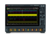
The MXR608A delivers 6 GHz bandwidth across 8 analog channels, driven by an ASIC-based low-noise acquisition engine. Eight simultaneous channels mean TX lane, RX lane, 28V rail, 5V logic rail, discrete line, and clock reference are all live at once, with no switching and no missed correlations between signal domains.
The MXR608A decodes ARINC 429 and MIL-STD-1553 natively, converting raw waveform data into readable bus traffic without external software or a separate protocol analyzer. The procurement case is straightforward: one MXR608A replaces two 4-channel oscilloscopes plus a standalone protocol analyzer.
On a per-channel, per-capability basis, the consolidated instrument is the lower-cost configuration, and it eliminates the timing synchronization errors that come with running two scopes in parallel.
Radar Altimeter Analysis and RF Component Characterization
Pulsed radar signals and high-frequency passive components represent two of the most instrument-sensitive test problems in avionics work. A standard spectrum analyzer and a general-purpose network analyzer will both produce results here. They just won't produce correct ones.
Why Standard Spectrum Analyzers Miss Pulsed Radar Anomalies
Radar altimeter signals are pulsed RF. The anomalies that cause altitude misreads are transient events that exist for microseconds, far shorter than the sweep time of a standard spectrum analyzer.
A swept analyzer steps through frequencies sequentially, which means there are gaps in the timeline between each sweep. A transient that occurs in one of those gaps is never captured, never appears in the data, and never triggers a failure flag. The engineer sees a clean spectrum, passes the test, and the fault that will cause an altitude misread at 500 feet AGL goes to flight.
Gap-free streaming is the only way to close that gap. It means capturing 100% of the signal timeline with no gaps between acquisitions, so every microsecond of pulsed RF activity is recorded regardless of when it occurs. Without it, you're not testing the signal, you're sampling it and hoping the anomaly lands inside your acquisition window.
For context on how to evaluate spectrum analyzers against your specific application requirements, Keysight's buying guide covers the key specifications in detail.
N9030B PXA: Gap-Free Streaming for Radar Altimeter Work
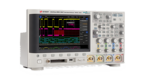
The N9030B delivers 75 dB SFDR with gap-free streaming up to 255 MHz analysis bandwidth. Both specs matter independently, and together they define the instrument's capability for radar altimeter work.
SFDR is the ratio of the RMS amplitude of the carrier frequency to the RMS value of the next largest noise or harmonic distortion component, as defined in the Analog Devices signal glossary.
In practical terms for radar altimeter testing, a lower SFDR analyzer masks anomalous signals behind its own noise floor and produces a false clean reading. At 75 dB, the N9030B keeps its own spurious content low enough that real anomalies in the signal under test remain visible.
The signal analyzer glossary provides additional reference on how SFDR interacts with other dynamic range specifications.
The gap-free streaming capability means the N9030B captures every microsecond of the signal timeline. Transient pulsed anomalies are recorded, timestamped, and available for post-processing.
The problem isn't just finding the anomaly, it's proving it exists with documented data. Gap-free streaming provides that documentation.
N5247B PNA-X: Filling the Antenna and Radome Characterization Gap
Antenna and radome characterization is the capability gap that almost no avionics bench addresses until a program forces the issue. No current aviation testing guide covers it in depth, which means most engineers discover the requirement late and scramble for lab time they didn't budget.
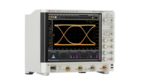
The N5247B covers 900 MHz to 67 GHz with the dynamic range required for accurate S-parameter measurement at K- and Ku-band frequencies, which is where radome characterization work lives. Measuring permittivity and loss tangent in radome materials at these frequencies requires a calibrated VNA with appropriate waveguide fixtures.
A 2024 study published in Membranes measured radome material permittivity and loss tangent at these frequencies using standard WR650 and WR137 waveguides, a Keysight VNA, and full-wave simulation.
The results confirmed that instrument calibration and dynamic range are the main constraints on measurement accuracy at K- and Ku-band.
For engineers who also need to characterize lower-frequency RF components and filter networks, the E5080B is a natural complement to the N5247B. It covers the lower end of the frequency range where the PNA-X is over-specified.
The network analyzer buying guide covers how to select between VNA options based on frequency range and application requirements. The full range of vector network analyzers available are listed on the product category page.
비교할 최대 3개 기기를 선택하세요
비교할 다른 기기를 선택하세요.
![]()
Starting at
비교할 다른 기기를 선택하세요.
![]()
Starting at
비교할 다른 기기를 선택하세요.
![]()
Starting at
Simulating the Aerospace RF Environment on the Benchtop
Testing avionics comms and navigation systems against a sine wave tells you almost nothing useful. The RF environment those systems operate in is spectrally complex, and your stimulus has to match it. This section covers the two instruments that handle that job on the bench.
E8267D PSG: Complex Modulated Signal Generation for Comms and Nav
GPS, TACAN, ILS, and VHF communication signals are not single-tone outputs. They use complex modulation that combines AM, FM, and arbitrary I/Q modulation.
This modulation maintains precise frequency accuracy and reflects the RF environment an avionics system encounters in service. Testing against anything simpler doesn't validate the system, it validates a simplified version of the system.
Labs without a dedicated vector signal generator typically assemble a workaround using three separate components:
- A signal generator
- An external baseband source
- A combiner
The problem with that approach is not the cost of the hardware, it's the timing errors and phase noise introduced at every junction in the signal chain. Those errors don't represent the real RF environment. They represent your test setup, and they can invalidate the measurement entirely.
The E8267D PSG eliminates that signal chain by integrating a wideband internal baseband generator with I/Q modulation up to 44 GHz in a single instrument. Satellite communications, navigation links, and tactical data links are all within range from one output, with no external combiner and no inter-stage phase noise.
The signal generator buying guide covers how to evaluate vector signal generators against specific modulation and frequency requirements. For engineers who need similar capability at a lower price point, the N5182B is a direct alternative worth evaluating alongside the E8267D.
M8190A: Benchtop Radar Target Simulation with Programmable Doppler Parameters
The standard approach to radar target simulation often involves a dedicated rack that occupies three rack units of lab space. It also requires a cabling configuration that can take hours to reconfigure and is difficult to document consistently. The M8190A collapses that into a single 2U arbitrary waveform generator on the bench.
The specific waveform capability is important in this context. A carrier frequency of 9.4 GHz falls within the X-band operating range for airborne low-range radar altimeters defined by RTCA DO-155. At this frequency, a Doppler shift of 1.26 kHz corresponds to a target closing velocity of 15 m/s, or about 50 ft/s.
That's the closing rate relevant for low-altitude terrain avoidance simulation. The M8190A programs this shift directly into the waveform definition at 12 GSa/s sample rate, with no external signal chain and no phase discontinuity between waveform segments.
Operationally this means the engineer defines closing velocity, range, and multipath delay as waveform parameters in software, then injects the resulting waveform directly into the radar receiver under test. The test is repeatable, documentable, and adjustable without re-cabling.
The 14-bit vertical resolution is what makes the multipath scenario tractable. Representing a strong direct-path return and a weak multipath echo simultaneously in the same waveform requires the dynamic range that 14-bit resolution provides. That's the scenario that causes altitude misreads near terrain, and it's the scenario your test needs to cover.
비교할 최대 3개 기기를 선택하세요
비교할 다른 기기를 선택하세요.
![]()
Starting at
비교할 다른 기기를 선택하세요.
![]()
Starting at
비교할 다른 기기를 선택하세요.
![]()
Starting at
Mastering DO-160 EMI Pre-Compliance In-House
Most avionics labs are well equipped for susceptibility testing. Amplifiers, injection probes, antennas. The stimulus side of DO-160 work is well covered by the market. The measurement side is not. This section covers the instrument that fills that gap.
What DO-160 Section 20 Actually Requires from Your Bench
DO-160G Section 20 covers radiated and conducted emissions testing. It defines the RF emission limits that avionics equipment must meet to satisfy airworthiness requirements. It specifies the measurement methodology, detector types, and frequency range your instrumentation must cover to produce valid results.
Pre-compliance testing is the internal checkpoint before that process begins. The objective is straightforward. Find and fix emissions problems on your own bench before committing to a third-party certification run that costs $20,000 to $50,000.
Every failure you catch in-house is a re-test you don't pay for at the certified lab. Every failure you miss is one you will pay for, on someone else's schedule, at someone else's rates.
Understanding what EMI testing actually measures, and how it relates to broader electromagnetic compatibility requirements, is the starting point for specifying the right receiver for this work.
N9048B PXE: Time-Domain Scanning for Rapid Emissions Diagnosis
Every competitor guide in this space covers susceptibility hardware: amplifiers, injection probes, antennas. None of them cover the receiver that actually diagnoses where an emission originates. The N9048B is that instrument.
A traditional swept EMI receiver steps through the frequency range one narrowband segment at a time. Finding a single emission spike with that approach can take hours, because the receiver has to work through the entire frequency range sequentially before the picture is complete.
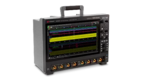
Time-domain scanning changes the architecture entirely. The N9048B scans the full frequency range simultaneously, compressing a multi-hour swept measurement into seconds and surfacing emission spikes immediately rather than at the end of a long sequential sweep.
The DO-160 Section 20 relevance is direct. The N9048B covers the required frequency range and implements the detector types specified by DO-160 for valid pre-compliance measurement: peak, quasi-peak, and average.
Those detector modes are not optional for DO-160 work. A receiver that doesn't support all three cannot produce results that map to the standard's acceptance criteria.
Contact a Keysight account manager for a cost comparison specific to your lab and program scope.
비교할 최대 3개 기기를 선택하세요
비교할 다른 기기를 선택하세요.
![]()
Starting at
비교할 다른 기기를 선택하세요.
![]()
Starting at
비교할 다른 기기를 선택하세요.
![]()
Starting at
Why Keysight Used Is the Right Source for Aviation-Grade Benchtop Equipment
The assumption that used test equipment can't meet aerospace quality system requirements is the single most common reason avionics labs overspend on new hardware. It depends entirely on the source.
| Equipment Tier | Refurbishment Source | Calibration Documentation | Firmware | Warranty |
|---|---|---|---|---|
| Keysight Premium Used | Keysight Penang manufacturing facility, 101-point quality check | Current calibration certificate, traceable to national standards | Updated to current release | Same as new Keysight instrument² |
| Standard Keysight Used | Keysight tested and verified | Calibration available on request | Current | 90-day warranty, extendable via KeysightCare |
| Broker-sourced used | Third-party or unknown | Often absent or non-traceable | May be outdated | Typically none or limited |
Equipment Tier
Refurbishment Source
Calibration Documentation
Firmware
Warranty
Keysight Premium Used
Title
Keysight Penang manufacturing facility, 101-point quality check
Keysight Penang manufacturing facility, 101-point quality check
Title
Current calibration certificate, traceable to national standards
Current calibration certificate, traceable to national standards
Title
Updated to current release
Updated to current release
Title
Same as new Keysight instrument²
Same as new Keysight instrument²
Standard Keysight Used
Title
Keysight tested and verified
Keysight tested and verified
Title
Calibration available on request
Calibration available on request
Title
Current
Current
Title
90-day warranty, extendable via KeysightCare
90-day warranty, extendable via KeysightCare
Broker-sourced used
Title
Third-party or unknown
Third-party or unknown
Title
Often absent or non-traceable
Often absent or non-traceable
Title
May be outdated
May be outdated
Title
Typically none or limited
Typically none or limited
Keysight Premium Used instruments are refurbished at the same Penang facility that manufactures new Keysight instruments, pass a 101-point quality check, and ship with current calibration documentation that satisfies AS9100 and DO-160 traceability requirements.
For engineers evaluating total cost of ownership, the Keysight Premium Used program is the starting point. Keysight Premium Used instruments ship with the same warranty as new. Standard Keysight Used includes a 90-day warranty, extendable through KeysightCare.
2Varies by model and region.
The Complete Aviation Benchtop Instrument Checklist
| Application | Instrument | Critical Spec | Primary Application | Keysight Used Availability |
|---|---|---|---|---|
| ARINC 429 / MIL-STD-1553 bus decoding | MXR608A | 8 analog channels, 6 GHz BW, ASIC-based low-noise acquisition | Multi-lane bus fault correlation and protocol decode | Premium Used |
| Radar altimeter anomaly capture | N9030B PXA | 75 dB SFDR, gap-free streaming to 255 MHz | Transient pulsed RF capture and spectral analysis | Premium Used |
| Antenna and radome characterization | N5247B PNA-X | 900 MHz to 67 GHz, high dynamic range S-parameter measurement | K- and Ku-band radome and antenna characterization | Premium Used |
| Comms and nav signal simulation | E8267D PSG | Wideband I/Q modulation to 44 GHz, internal baseband generator | GPS, TACAN, ILS, and VHF comms stimulus generation | Premium Used |
| Radar target simulation | M8190A AWG | 12 GSa/s, 14-bit resolution, programmable Doppler parameters | Benchtop radar target and terrain avoidance simulation | Premium Used |
| DO-160 Section 20 pre-compliance | N9048B PXE | Time-domain scan, peak/quasi-peak/average detectors, 1 Hz to 44 GHz | Radiated and conducted emissions diagnosis | Premium Used |
Application
Instrument
Critical Spec
Primary Application
Keysight Used Availability
ARINC 429 / MIL-STD-1553 bus decoding
Title
MXR608A
MXR608A
Title
8 analog channels, 6 GHz BW, ASIC-based low-noise acquisition
8 analog channels, 6 GHz BW, ASIC-based low-noise acquisition
Title
Multi-lane bus fault correlation and protocol decode
Multi-lane bus fault correlation and protocol decode
Title
Premium Used
Premium Used
Radar altimeter anomaly capture
Title
N9030B PXA
N9030B PXA
Title
75 dB SFDR, gap-free streaming to 255 MHz
75 dB SFDR, gap-free streaming to 255 MHz
Title
Transient pulsed RF capture and spectral analysis
Transient pulsed RF capture and spectral analysis
Title
Premium Used
Premium Used
Antenna and radome characterization
Title
N5247B PNA-X
N5247B PNA-X
Title
900 MHz to 67 GHz, high dynamic range S-parameter measurement
900 MHz to 67 GHz, high dynamic range S-parameter measurement
Title
K- and Ku-band radome and antenna characterization
K- and Ku-band radome and antenna characterization
Title
Premium Used
Premium Used
Comms and nav signal simulation
Title
E8267D PSG
E8267D PSG
Title
Wideband I/Q modulation to 44 GHz, internal baseband generator
Wideband I/Q modulation to 44 GHz, internal baseband generator
Title
GPS, TACAN, ILS, and VHF comms stimulus generation
GPS, TACAN, ILS, and VHF comms stimulus generation
Title
Premium Used
Premium Used
Radar target simulation
Title
M8190A AWG
M8190A AWG
Title
12 GSa/s, 14-bit resolution, programmable Doppler parameters
12 GSa/s, 14-bit resolution, programmable Doppler parameters
Title
Benchtop radar target and terrain avoidance simulation
Benchtop radar target and terrain avoidance simulation
Title
Premium Used
Premium Used
DO-160 Section 20 pre-compliance
Title
N9048B PXE
N9048B PXE
Title
Time-domain scan, peak/quasi-peak/average detectors, 1 Hz to 44 GHz
Time-domain scan, peak/quasi-peak/average detectors, 1 Hz to 44 GHz
Title
Radiated and conducted emissions diagnosis
Radiated and conducted emissions diagnosis
Title
Premium Used
Premium Used
No avionics lab needs all six instruments on day one. Lab managers should start with their primary test focus and build from there.
If your program is bus-heavy, the MXR608A is the first acquisition. If DO-160 submission is the near-term pressure point, the N9048B pays for itself fastest. If radar simulation is the core requirement, the M8190A and N9030B are the logical starting pair.
Keysight account managers can build a phased acquisition plan tied to your program milestones and budget cycles, so capital expenditure tracks against program needs rather than being front-loaded against a wishlist.
비교할 최대 3개 기기를 선택하세요
비교할 다른 기기를 선택하세요.
![]()
Starting at
비교할 다른 기기를 선택하세요.
![]()
Starting at
비교할 다른 기기를 선택하세요.
![]()
Starting at
Build the Bench That Catches Failures Early
Flight line testers and anechoic chamber rentals dominate aviation testing discussions. Neither builds in-house capability. Neither helps an R&D engineer catch a DO-160 failure before it reaches a certified lab. This guide exists because that gap is real and the instrumentation to close it is available.
The six-instrument framework maps directly to the six problems avionics benches consistently fail to address.
The pre-compliance ROI point is simple. Engineers who build this bench find DO-160 failures in-house, on their own schedule, at bench cost. They don't find them at a certified lab, at $20,000 to $50,000 per re-test cycle, on a timeline they don't control.
If you're building out your bench, the used oscilloscope buying guide and the network analyzer vs spectrum analyzer comparison are useful next reads for narrowing your specification before you go to procurement.
비교할 최대 3개 기기를 선택하세요
비교할 다른 기기를 선택하세요.
![]()
Starting at
비교할 다른 기기를 선택하세요.
![]()
Starting at
비교할 다른 기기를 선택하세요.
![]()
Starting at
Whenever You’re Ready, Here Are
5 Ways We Can Help You
1
Browse our premium used network analyzers, oscilloscopes, signal analyzers and waveform generators
2
Call tech support US: +1 800 829-4444
Press #, then 2. Hours: 7am – 5pm MT, Mon– Fri
3
Contact our sales support team
4
Create an account to get price alerts and access to exclusive waitlists
5
Talk to your account manager about your specific needs
Frequently Asked Questions
Does DO-160 pre-compliance testing require ISO 17025 accredited calibration, or is commercial calibration sufficient?
Final third-party DO-160 certification requires ISO 17025-accredited calibration. In-house pre-compliance testing can use commercial calibration, provided the instruments carry documented traceability to national standards. Keysight Premium Used instruments ship with current calibration documentation that supports this traceability chain.
Can I upgrade the bandwidth or add software options to a used Keysight MXR608A after purchase?
Yes. Hardware options, applications, and software options can be added or removed according to your order configuration. Contact the Keysight Used Equipment Store team via the product page to confirm which upgrades are available for a specific unit before purchase.
What causes false ARINC 429 triggers on an oscilloscope if the differential voltage is correct?
Correct differential voltage does not rule out common-mode noise or ground loops. Both generate trigger events the oscilloscope cannot distinguish from real bus transitions. Adjusting trigger holdoff and using high common-mode rejection ratio (CMRR) differential active probes alongside the MXR608A's low-noise ASIC acquisition engine resolves this in most bench environments.
How do you export gap-free streaming data from the N9030B for post-processing?
The N9030B streams captured data to an external storage device. A RAID array is recommended for sustained 255 MHz analysis bandwidth captures, which generate large contiguous files. Data exports in standard formats compatible with MATLAB and Python signal processing workflows for offline anomaly analysis.
How do you synchronize the M8190A AWG with an external radar receiver to measure processing latency?
Use the M8190A's marker outputs to generate a TTL pulse at T=0, the precise moment the waveform segment begins. Route this pulse to the trigger input of the receiver under test. The time delta between the marker pulse and the receiver's detection output is the processing latency, measurable directly on a time-correlated oscilloscope channel.
Can the N9048B PXE time-domain scan be paused to investigate a specific transient emission?
Yes. After a wideband time-domain scan identifies an emission spike, the N9048B transitions to real-time analysis on that specific frequency for detailed characterization. This eliminates the need to run a full sequential sweep again. The problem frequency is already identified and ready for deeper investigation.
Why do avionics systems fail DO-160 Section 20?
Most Section 20 failures trace back to two places: insufficient filtering on power lines and poor shielding at the enclosure-to-connector interface. Both are diagnosable on the bench before you spend $40,000 finding out at a certified lab.