What are you looking for?
PathWave Advanced Design System (ADS) 2020 Update 2.0 Product Release
Highlights
PathWave ADS 2020 Update 2.0 delivers solutions and more for:
- High-Speed Digital (HSD) Design
- Electromagneitc (EM) Simulation
- Circuit Simulation
- Power Electronics Design
- Design and Technology Management
- Design Editing
Description
![]() PathWave ADS 2020 Update 2.0 delivers solutions and more for challenging High-Speed Digital, RF & Microwave and Power Electronics designs including the following.
PathWave ADS 2020 Update 2.0 delivers solutions and more for challenging High-Speed Digital, RF & Microwave and Power Electronics designs including the following.
High-Speed Digital Design
SerDes
- Introduced the E-O-E (Electrical-Optical-Electrical) integrated work flow with VPIphotonics for Datacom and Telecom markets. This enables the users to consider the optical channel effect in the design of the end-to-end link analysis, such as:
- Nonlinear wavelength-dependent transfer function of Electro-Absorption Modulators (EAM)
- Nonlinearity
- Relative Intensity Noise (RIN)
- Fiber attenuation
- Dispersion
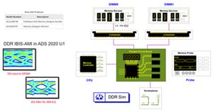
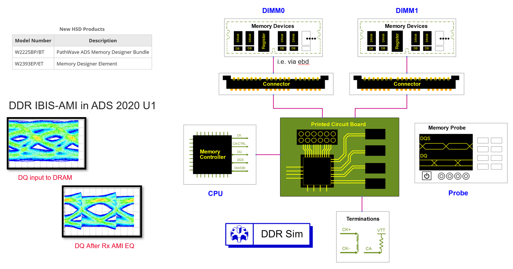
DDR/Memory
- New DDR5 and LPDDR5 solutions with IBIS-AMI modeling for equalizations
- Jitter tracking for optimal DFE clocking with internal phase interpolator training
- Automated DDR5 compliance test on simulated waveforms
- Streamlined memory design workflow such as integrated package setup in to Controller and Memory to reduce wiring
- Controller, Memory, and Termination GUI improvement and group editing for DDR_Termination component for better usability

SIPro/PIPro/Via Designer
- Context-Aware Signal Name Matching algorithms in SIPro
- Added delay plot in the results window.
- Added dc frequency (0 Hz) support for Logarithmic frequency plan in Via designer.
- Added option to set number of samples for siodump.
EM Simulation
General
- Added support for Teardrops in EM Simulation flow
RFPro
- Enabled RFPro flow for Custom Compiler
- Improved the speed of opening and component change role in RFPro
Circuit Simulation
General
- Modified the custom rule regular expression
- Changed the rise time and fall time to 0.2 dq UI
- Use custom rule when specified without having to add it to preset
- Added the list of BER and "Calculate contour at multiple BER" option
- Fixed the DDR_PCB table resize issue
- IBIS model selection now displays the full model name
- Fixed the issue where two DCD implementations reports shows different results
- WidthAtBER now gives correct results when the Density is not at center of 2UI in the IBIS-AMI Channel simulation
ElectroThermal
- ETH now consumes the raw TransientVars::step_reduction_factor, without processing (clamping etc.)
- Fixed the reuse model extraction while using encrypted thermal technology
Power Electronics
Model from datasheet
- Added a template to extract a model from a Power MOSFET datasheet
- Added an example workspace to demonstrate model extraction from a Power MOSFET datasheet
Added a generic power MOSFET component to the Power Electronics library
Fixed a bug in the IGBT example workspace
Power Electronics Professional (PEPro)
- Fixed a bug in the show/hide button in the PEPro Layer Display Settings Panel
- Fixed a bug in the information icon in the select dataset dialog in circuit excitation
- Fixed a bug in the closed loop buck converter example workspace
- Fixed a bug in the field scale properties
Design and Technology Management
Data Display
Expression Manager is a docking window that displays all equations and trace equations in a table. You can now use one Expression Manager window for multiple data display windows opened. Following are the improvements:
- Reference updating, selection and added new right click options
- Selecting dependent option now prompts you a warning about deactivated dependent equation
- Selecting dependent equation now does not jump to selection by default
Design Editing
Added the following AEL functions:
- Tear drop AEL Functions to add, modify, and remove tear drop to selection. For more information, see Teardrop Functions
- db_find_inst_term_by_name() - Finds and returns an inst term given an instance object and the name of the instance terminal
- db_set_edge_area_port_of_fig() - Sets the pin fig’s edge/area port to the term passed in. If a term number of 0 or an empty term name is passed in, the fig’s edge/area port will be cleared
Design Import/Export
- Added support for import of netlists with diode model temperature coefficient parameters
- Added support for import of LTspice netlists with component values enclosed in curly braces
Design Rule Check (DRC)
Assura DRC
- Provided the configuration to set default components for artwork (pcell) generation of dependent components
Calibre DRC
- Added functions to configure rule file and rule folder
Verification Test Bench (VTB)
The Single Port VTB (only Source) simulation is now supported. Now, you can create complex modulated sources in SystemVue and use with ADS Circuit Envelope.
Note: With the default settings in SystemVue VTB, SystemVue manages the time scale of the simulation. In general, when the VTB has sinks, the sinks are set in such a way (inside the SystemVue workspace) that the stop time of the simulation is automatically set to retrieve the amount of data necessary to calculate the requested figure-of-merit. In the case where the VTB does not have sink (input-only VTB), the stop time may be not clearly set in the SystemVue workspace. In this case, this may result in a long simulation if the stop time is large.
By default, no warning is issued because the simulator does not know the stop time of the SV workspace before running it.
If the user sets a value different from 100n (excluding 0), the envelope controller becomes the controller. In this case, the simulation will stop at the first stop time it reaches (either the stop time set in the Envelope controller or the stop time set in the SystemVue workspace). Setting a custom stop time may be useful to debug general VTBs (without having to run the full timeframe) and may be required for input-only VTBs to set a realistic stop time
Note: When you set 100ns, for back compatibility, the simulator ignores it. stop=100n was the value set in the controller when you put it on the schematic. To be back compatible, stop time = 100n means that we let the SV workspace control the timing.
From ADS 2017, to install files that are required for the VTB functionality you need to download a separate VTB installer (for Windows only). For Linux, the VTB installer is bundled with ADS installer.
- It is recommended to download compatible ADS and VTB installers to the same directory. After the download, run the ADS installer. This process will automatically install the VTB functionality.
- If you have already installed ADS and find VTB functionality is missing, then you need to download and install the VTB.
- Upgraded SystemVue 2018 Update 1 engine in ADS.
- Updated the following VTBs:
- 3GPP_NR_DL_Tx_Source
- 3GPP_NR_DL_Tx
- 3GPP_NR_UL_Tx_Source
- 3GPP_NR_UL_Tx
- Updated the following VTBs:
- The modifications are as below:
- Support Test Models defined in 3GPP TS 38.141 V1.2.0(2018-11) for NR downlink examples
- Support Common Configuration defined by Table 6.1-1 in 3GPP 38.521-1/38.521-2 for NR uplink examples
- Speed up the EVM measurement by reducing the measurement length to 1 subframe
- Add ACLR measurement
Note: SystemVue engine used by ADS 2020 Update 1.0 is evolved based on SystemVue 2018 Update 1.0 by fixing some critical issues. Therefore, although running the above VTB examples with ADS 2020 Update 1.0 can give correct results, running them with SystemVue 2018 Update 1.0 may end up with errors or wrong results. If you need to make changes to these examples, it is recommended to open and modify them with SystemVue 2018 Update 1.0, and then import them back into ADS, and observe the results by running ADS 2020 Update 1.0.
ADS 2020 Update 1.0 only supports the import of Custom VTB (SystemVue workspace) created using SystemVue 2018 and SystemVue 2018 Update 1.0.
Learn More
View other ADS Product Versions.
Return to PathWave Advanced Design System (ADS)