Dedicated Short Range Communications (DSRC) deployment is coming for vehicle-to-vehicle (V2V) communications. Module vendors and vehicle system integrators have commenced working in the design stage and are finding a series of issues impacting their module design or system integration that are out of their control (due to environment variations affecting vehicles on the road).
The environment changes depend on where the vehicles are located, i.e. rural, urban, or highway areas. In addition, the DSRC IEEE 802.11P standard specifies the V2V radio channel conditions include rural line-of-sight (LOS), urban approaching LOS, street crossing non-line-of-sight (NLOS), highway LOS, and highway NLOS.
Module vendors, car companies, and system integrators must devise a way to put together systems that operate with high connectivity and reliability in all these environments. Ignoring this challenge prior to deployment can cause market deployment delays and additional implementation cost.
One way to address the above challenge is to have design processes that can include a wide variety of environmental scenarios, to ensure a robust design in reducing the number of costly field road tests required. To achieve this, we need a virtual software platform emulating the environment, and meet the IEEE 802.11P physical layer requirements. The good news is, this virtual road test platform is already a reality.
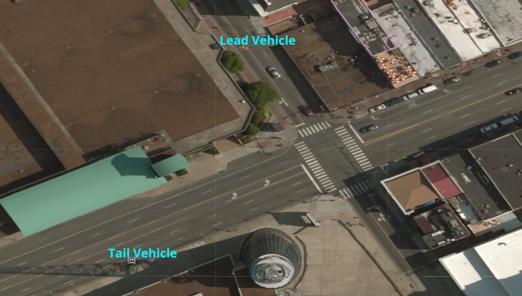
Consider the radio channel for a pair of vehicles with NLOS at a major street crossing (as seen in Figure 1). Initially, the two cars don’t have communication until they clear the corner building. Once this is completed, performance challenges are primarily equated to the distance between the cars, relative speed, and angle between the vehicles. These physical parameters are directly responsible for signal loss, delay, doppler shift, etc. The communication system needs to overcome for a reliable transfer of information. System designers are then faced with the possibility of having to perform field driving tests in many locations with non-repeatable conditions. These include weather, total number of vehicles, and interferers which are not controllable and can vary significantly with time. Having a software platform to emulate this in a virtual environment will help pre-deployment design and integration of the different modules and components for the V2V communication system since all these variables can be controlled. A virtual software strategy that includes IEEE 802.11P standard compliant physical layer emulation will contribute to the system design, making the design more reliable and robust.
The physical properties of the vehicle will also impact the communication link. Consider the location of the communication radio antenna on the vehicle. It’s worth noting there’s a limited set of locations where the antenna can be placed. Take for example, a dipole antenna which has a typical radiation pattern as shown in Figure 2a. The same antenna (when mounted on a car) will have the pattern altered (as seen in Figure 2b) due to the presence of the vehicle body. As the vehicle moves in the NLOS scenario under consideration, the angle between the vehicles changes, which in turn means the receive and transmit antennas line-of-sight angle also changes. As the angle shifts, so does the overall antenna gain between transmitter and receiver. This gain change would not occur if the perfect dipole antenna pattern had been preserved once the antenna was mounted. Antenna gain changes coupled to a communication channel that’s also changing due to the relative movement of the vehicles, means keeping track of all these dynamics—this will involve more than just a classical channel link analysis.
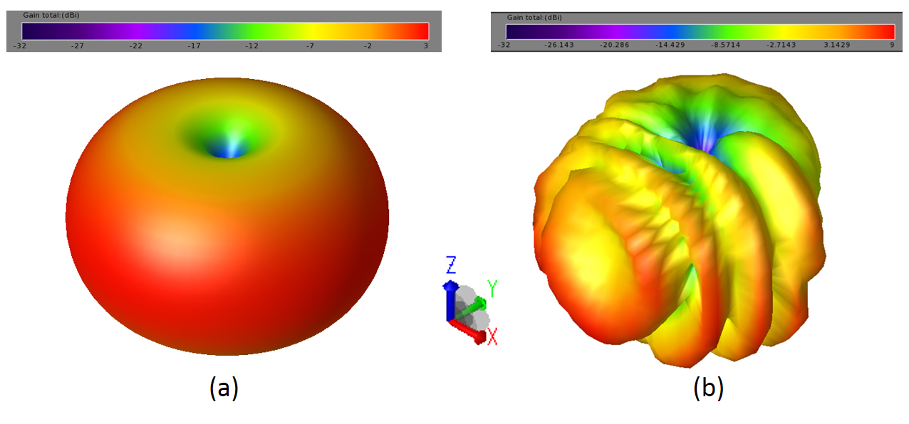
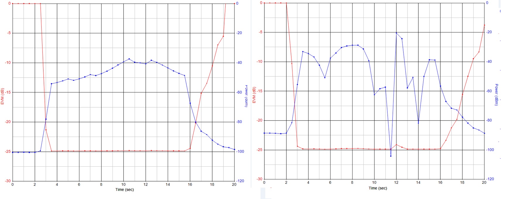
A virtual scenario simulation platform allows for capturing the physical 3D environment in which the vehicles are moving over time. For the antenna pattern, two cases were analyzed—the unmounted dipole and car mounted dipole antenna (see Figure 2), constituting a full 3D simulation package. Shown in Figure 3, are the setup and results of the virtual test drive. The 3D patterns from transmit and receive antennas (included in the simulations) aren’t explicitly shown, but are included as part of the transmitter and receiver modules. The results show average received power and error vector magnitude (EVM). Two test drives were performed: (i) ideal dipole antenna and (ii) car-mounted dipole antenna over the same route in each test. Immediately, the effect of the corner building (see Figure 1) is apparent as the signal average power increases once the cars clear the building. Impact from mounting the antenna on the car is observed—more received signal strength variability as the two cars move in this urban environment in this test. Signal variability analysis like this gives the receiver designer insights into how much dynamic range the receiver requires.

Virtual driving scenario analysis with this software integration allows for varying position, speed, and acceleration with many possible varied scenarios and conditions. Design criteria such as component variability or statistical analysis are also possible. Techniques used for this analysis are especially well capable of performing spatially aware interference with many more transmitters and receivers included in the analyses. Standards will continue to be modified for improved data rate transmission and reliability. These standard changes can be supported by this approach as these analysis techniques are adopted by the different standard bodies.
Often, engineers encounter issues with the work flow from system design to validation and test efforts as the design and test teams cannot agree on the validity of the test results. Factors affecting these are conditions under which the tests are performed. Such test issues can be alleviated or even eliminated if the data test vectors (e.g. modulated I and Q data) were the same as those used for the design phase of the product lifecycle. This data sharing would also benefit the collaboration between module vendors, engineering disciplines as RF transmitter and receiver, along with antenna and DSP design teams. An approach like this allows all teams to visualize the others’ strengths, limitations, and the impact to their section on the system. Having test vectors which can include scenario environment driving conditions (i.e. a non-constant time varying dynamic channel properly characterized) can contribute to a smooth transition from design through validation and implementation.
The virtual platform is based on the link between Keysight Technologies Inc. SystemVue Software and Analytical Graphics Inc. STK Software, and the antenna analyses were performed using EMPro from Keysight Technologies Inc.
