
SDN-Based Network Slicing for 5G Transport Networks
By Anirban Bhattacharya | Flexible Algorithm (Flex-Algo) is a hot new technology in the segment routing area. It optimizes the physical network with slices based on different constraints and auto-steers traffic via any topology/path based on operator-defined logic. Flex-Algo is the latest addition to segment routing traffic engineering and applies to both Segment Routing (SR) MPLS and IPv6 data plane. This is expected to be one of the key technologies to enable software-defined networking (SDN) slicing infrastructure for 5G transport networks.
Technology Overview
Flex-Algo allows interior gateway protocol (IGP) alone to compute constraint-based paths over the network. It enables traffic engineering path calculations without involving a network controller and provides simplified operation by provisioning dynamic constrained paths based on a single SR label. Let us take an example of a dual-plane network use-case to explain how Flex-Algo works vis-a-vis regular Segment Routing Traffic Engineering (SRTE) technology.
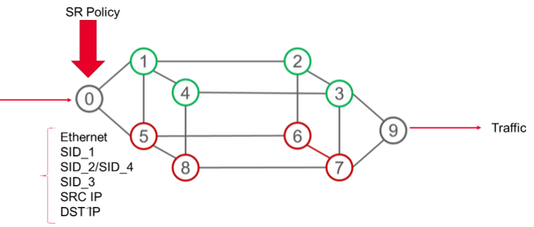
Sample topology of routing a green and a red service through a network using an SR policy
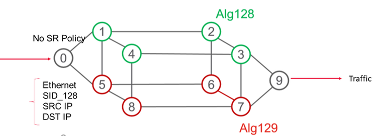
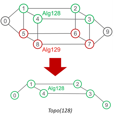
Sample topology of routing a green and a red service through a network using Flex-Algo
In this dual-plane network, let us say we want to restrict traffic for the green service to the top 4 nodes, whereas for the red service, the bottom 4 nodes. Service here could mean anything like low delay, high bandwidth, or a path through nodes in specific geographic locations.
In Flex-Algo, every node can advertise their participation in a specific algorithm. Traffic forwarding can be restricted to only those nodes or links participating in that algorithm. The ingress node can now forward traffic with just one SID identifying the Flex-Algo, and packet forwarding will be taken care automatically by the IGP according to forwarding rules for that plane. Also, the ingress node does not need to know the full traffic engineering (TE) path.
Exploring Definitions
“Algorithm” refers to the way to calculate a path to a destination, like shortest path first (SPF) using a Dijkstra algorithm in ISIS/OSPF. Additionally, it may also have topological constraints included.
“Flexible” because it is up to the operator to define an algorithm suitable for the operator’s network. In IETF draft-ietf-lsr-flex-algo, each Flex-Algo is defined as a combination of three parameters. This definition is called FAD (Flex-Algo Definition). These three parameters are:
- Constraints on the topology (e.g., use a particular set of nodes)
- Calculation type (e.g., SPF, Constrained SPF)
- Metric type (default IGP metric, link delay as defined by RFC 8570, etc.)
Each flexible algorithm is identified by a number, in the range of 128-255. The definition is valid within an IGP domain. An operator can use Flex-Algo #128 to identify a network slice for “minimum delay and avoid X,Y,Z nodes”. Another operator can use the same Flex-Algo #128 to identify a network slice to “minimize IGP metric and avoid links X-Y, Y-Z”.
Summary of Flex-Algo Operations
Let me summarize Flex-Algo operations below. Here I have taken an example of ISIS as an IGP, but these are applicable to OSPF as well.
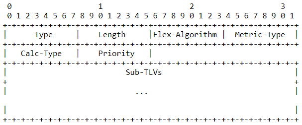
- Advertising Flex-Algo Definition (FAD): FAD is a sub-TLV of ISIS Router Capability TLV (242). Not all routers are required to define FAD. Only one router needs to define it and flood it in ISIS area. If multiple routers define FAD for a Flex-Algo, then the highest priority (or system ID as tie-break) determines which definition is selected. The FAD sub-TLV can have sub-sub TLVs to identify topological constraints. These sub-sub TLVs are used to exclude or include links in a Flex-Algo topology by their Extended Admin Group affiliation. Below is the format of ISIS FAD sub-TLV:

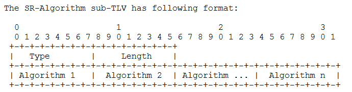
- Announcing Flex-Algo Participation: Each router interested to take part in a Flex-Algo needs to advertise the Flex-Algo in its SR-Algorithm sub-TLV under Router Capability. Also, node reachability prefixes should be advertised with prefix-SIDs for each Flex-Algo in SR MPLS. For SRv6, separate locators are advertised per Flex-Algo. These settings are usually provisioned by an operator in each router. Below is the format for the SR algorithm sub-TLVs:
- **Setting Link Attributes: **Flex-Algo makes use of several TE metrics configurable in a link. Extended Admin Group is one such setting defined by RFC 7308 that is used to apply constraints on a topology. There are other metrics including IGP Metric, Minimum Unidirectional Link Delay (RFC 8570), and TE Default Metric (RFC 5305) that can be used by Flex-Algo to calculate TE paths.\
- Co-Existence with Other Traffic Engineering Applications: In scenarios where other traffic engineering applications like RSVP-TE and SR Policy also use the same link, it is possible to assign application-specific values for each TE attribute. IETF draft draft-ietf-isis-te-app defines these advertisements. Flex-Algo can optionally make use of these application-specific advertisements. The Flex-Algo draft reserves a bit (X-bit) for itself in the Link Attribute Applications Registry.\
- Flex-Algo Computation: Each node (N) runs multiple Dijkhsetra algorithms, one for each Flex-Algo. N first prunes the nodes that are not member of that Flex-Algo (K). N also prunes any link that is excluded by K. This results in a topology for K. N then computes SPF tree on Topo(K) with metric defined by K.
- ECMP and Backup Path Installation: Each router calculates ECMP and backup paths including TI-LFA paths based on the reduced Flex-Algo topology. This is an inherent advantage of Flex-Algo technology. The SR ingress router does not need to bother about adjusting to network failures while ensuring service SLA. Traffic gets re-routed automatically within the Flex-Algo plane in case of failures.\
- VPN Overlays on Flex-Algo: So far, we have seen how IGP is used to set up the underlay SR Flex-Algo network. Now let us look at how BGP is used to provide overlay VPN services on top of this SR Flex-Algo underlay. Flex-Algo works on both MPLS and SRv6 data planes. Let me illustrate with the example of a Layer-3 VPN service over the Flex-Algo network.

Reference topology for L3VPN over SR MPLS
There are some routers in the IGP plane where Flex-Algo is configured. PE1 and PE2 are ingress and egress routers. PE2 advertises participation in Flex-Algos 128, and 129, along with the SIDs to reach it via those algorithms. That information is propagated in IGP ISIS. Ingress PE1 has paths to reach PE2 via these Flex-Algos. For example, PE1 will use SID2 if it wants to reach PE2 in Flex-Algo 129.
For the L3VPN overlay, egress router PE2 sends VPN routes in BGP along with a color value. The color value identifies the service PE2 wants for that VPN route. Ingress router PE1 needs to have a way to associate the color to a Flex-Algo. This can be done through configuration in PE1.
When data packets arrive at ingress PE1 for the VPN, it encapsulates the packet with two SIDs. The first SID is the VPN SID advertised by PE2 for that route. The second SID is the one advertised by PE2 for the Flex-Algo indicated by the color value in VPN route. The packet is then sent to the next hop for reaching PE2 over this Flex-Algo. Intermediate routers forward the packet based on the outer Flex-Algo label. When the packet reaches PE2, it is decapsulated and the original frame is sent out to the VPN destination.
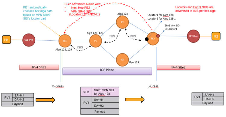
VPN SID is mapped to different locators indicating different algorithms
This topology is similar to the SR-MPLS case from the above example. For SRv6, a different locator is advertised in ISIS for each Flex-Algo. Each locator can be thought of as tied to one Flex-Algo. Therefore, BGP VPN overlays can use SRv6 VPN SIDs mapped to these locators to specify TE requirements for a VPN route. In the above example, the egress PE2 may use an SRv6 VPN SID mapped to Locator1 to indicate that it wants the service mapped to Flex-Algo 128 for the VPN routes. This SRv6 SID will be included by PE2 in the BGP route advertisement. The function type of the SID could be either DT4 or DX4 for IPv4 L3VPN. Ingress PE1 can identify the desired algorithm since the SRv6 VPN SID received in BGP is part of the Locator1 information it received in IGP ISIS. PE1 inserts an IPv6 header in the incoming packets with this SRv6 VPN SID as the destination IPv6 address. The SR Header (SRH) may be omitted since there is only one SRv6 SID in this case. The packet is then sent to the next hop as per the Flex-Algo 128 path calculation.
Test Flex-Algo with IxNetwork
Flex-Algo requires multiple technologies working in tandem to achieve the purpose of the flexible algorithm. It requires setting up the underlay network by advertising the Flex-Algo definition, router participation, TE settings, etc. IGP then runs multiple instances for calculating routing tables per Flex-Algo. Number of algorithms supported, number of routes supported per Flex-Algo, and total route scale across Flex-Algos are important performance indicators of the implementation. VPN services and other applications can then use the underlay network “slice” to fit each specific need for end-to-end service delivery. A thorough test of each component and the integration of multiple components need to be conducted at multiple levels to ensure seamless operation. The performance also needs to be assessed for individual components and at the system level to optimize the overall network capacity and service delivery.
As a test tool provider, Keysight is actively engaged in cutting-edge technology development. We are working with leading network equipment manufacturers (NEMs) and service providers to help in early development and trial cycles. With Keysight’s IxNetwork Flex-Algo solution, customers can simulate Flex-Algo networks with many nodes supporting multiple algorithms to validate device under test (DUT) functions in different roles (ingress node, intermediate node, and egress node) and assess the performance for both control- and data-plane.
The IxNetwork Flex-Algo simulation includes ISIS underlay and BGP VPN overlay for both SR MPLS and SRv6 data planes. It can auto-generate traffic based on control-plane information to validate forwarding performance.
Below are two use cases of testing the topologies described in the previous section.
Use Case 1: L3VPN Over SR-MPLS with Flex-Algo, Where DUT is Transit and Egress
- Here DUT is being tested for transit and egress functionality in an SR MPLS Flex-Algo network. DUTs P1, P2, P3, and PE2 are connected in a ring topology. IxNetwork (shown as the IXIA symbol) emulates ingress PE1, and CE2 is connected to egress PE2. Please refer to the topology diagram under the L3VPN over SR-MPLS with Flex-Algo section.
- The PE1 router is configured to advertise FAD for flexible algorithms in ISIS IGP. Here let us assume PE1 is advertising the FAD for algorithms 128, 129, and 130.
- PE1 advertises a loopback address in ISIS SR with three prefix SIDs, which belong to both flexible algorithms 128 and 129. P1 and PE2 also advertise both algorithms. But P2 and P3 will not be advertising participation in algorithms 129 and 128 respectively. All routers also participate in the default algorithm 0. ISIS Learned information in Ixia PE1 can be used to verify these advertisements from DUT.
- PE1 connects BGP L3VPN to the egress DUT PE2 and exchanges VPN routes. Let us say PE2 sends three VPN routes with color 100, 101, 102. The BGP VPN learned information in ingress PE1 can be used to verify the routes are received from DUT with correct color value.
- A template is installed in the Ingress PE1 to match these colors to flexible algorithm values. For example, color 100 matches Flex-Algo 128, color 101 matches Flex-Algo 129, and so on.
- When the user creates traffic streams for the VPN destinations, IxNetwork creates the VPN packets automatically with 2 labels. Outer label is the Flex-Algo label. It is the SR SID advertised in loopback of PE2 for the Flex-Algo corresponding to the color value in the VPN route. Inner label is the VPN label advertised for the VPN prefix.
- The encapsulated VPN packet will arrive at transit router P1 first. Based on the outer Flex-Algo label, P1 needs to send this packet to the correct next hop as per Flex-Algo topology.
- Egress PE2 decapsulates these packets and forwards to the VPN destination CE2 connected behind PE2. CE2 here is an IxNetwork emulated device that can be used to verify the receiving traffic.
- This can be scaled up easily with multiple algorithms and many egress PE routers, VPNs, and CEs for scale and performance testing. IxNetwork can also be used to scale egress PE routers for similar testing of DUT as ingress PE router.
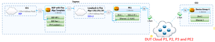
Use Case 2: L3VPN over SRv6 with Flex-Algo, Where DUT is Ingress Router

- Here DUT is ingress PE1 in an SRv6 Flex-Algo network. Please refer to the topology diagram under the SRv6 in IPv4 L3VPN Over SRv6 with Flex-Algo section.
- IxNetwork emulates the topology of P1, P2, P3, and PE2 routers. It also emulates CE1 connected to ingress PE1.
- Any of the routers can be configured to advertise FAD. Here, let us assume P1 is advertising FADs for algorithms 128, 129, and 130. Other routers can also be configured with the same FAD with different priority values to test tie-break logic in the DUT.
- All routers advertise different locators for each Flex-Algo. They can also optionally advertise multiple adjacency END.x SIDs per interface for each Flex-Algo. IxNetwork emulated P1, PE2, and DUT PE1 advertises locators for both Flex-Algos 128 and 129. But IxNetwork-emulated P2 and P3 do not advertise Flex-Algos 129 and 128 respectively. All routers also participate in the default algorithm 0. ISIS learned information in P1 can be used to validate advertisements from the DUT.
- PE1 connects BGP L3VPN to the egress DUT PE2 and exchanges VPN routes. Here, the locator portion of advertised SRv6 VPN SIDs (DT/DX) identifies the Flex-Algo service associated with the VPN route. BGP VPN learned information in PE2 can be used to validate the SRv6 VPN SID sent by the DUT for each VPN route.
- The user creates traffic streams from CE1 toward the VPN destinations behind PE2. These un-encapsulated packets arrive at DUT PE1. PE1 looks up the SRv6 VPN SID based on the destination of the packet. The SID here belongs to a Flex-Algo topology. PE1 then forwards the packet with an outer IPv6 header where the SRv6 VPN SID as used as the destination IPv6 address. It may optionally contain an SRH header.
- Ingress PE1 DUT forwards these encapsulated packets toward the VPN destination CE2 emulated in the IxNetwork port. The IxNetwork port can be used to validate DUT forwarding using traffic statistics and packet capture.
- This can be scaled up easily to test many ingress PE routers, VPNs, and CEs with different topology shapes for scale and performance testing. IxNetwork can also be used to scale ingress PE routers for similar testing of the DUT as egress PE router.