
When the Press Started to Bend: A Story About Bringing Reality Back into Stamping Simulation
For decades, stamping engineers have trusted simulation as their digital crystal ball.
We build our dies, define our blank, position everything carefully in the press station, and hit “run.” We iterate. We refine. We correct thinning. We improve draw-in. We compensate springback. Eventually, the forming limit diagram turns green, the contact looks healthy, and we move forward with confidence.
But then comes tryout.
And sometimes, reality disagrees.
The part does not fully close. The radii are slightly off. Springback is higher than predicted. Surface quality suffers. The press behaves differently from what the simulation suggested. And suddenly, the green part on the screen becomes a yellow or red part on the shop floor.
This story begins with a simple but uncomfortable realization: the press bends.
The Quiet Shift in Forming Reality
Over the years, the stamping environment has changed dramatically. Materials became stronger. Advanced high-strength steels increased forming loads significantly. OEMs began grouping more parts per stroke to improve productivity, which increased total press forces and introduced force imbalance. Operations were combined, trimming together with forming, reducing structural stiffness in critical tool areas.
Meanwhile, vehicles grew larger, but tool weight and cost constraints remained fixed. Reinforcement ribs had to be optimized more aggressively. Their number, location, and thickness became tighter compromises rather than conservative safety measures.
All these factors converged into one undeniable consequence: higher and more asymmetric forces acting on tools and press structures.
And when forces rise, structures respond.
The press frame deforms. The RAM tilts slightly. The bed and bolster deflect. The punch and die elastically bend. Even if those deformations are only a few tenths of a millimeter, they change contact conditions dramatically.
But in traditional forming simulations, including those performed in Keysight Stamping, tools and press are assumed perfectly rigid.
And that is where the story turns.

Example of grouping a hood inner and a hood outer in one die set.
The Illusion of Perfect Rigidity
The standard workflow is well known. The engineer prepares the geometry, defines the blank, installs the tools, runs the simulation, and iterates until the results look acceptable. Once formability, thinning, and springback are under control, the process moves forward to compensation and robustness studies.
All the while, the die, punch, blank holder, and press are treated as immovable, infinitely stiff objects.
In the digital world, everything closes perfectly at bottom dead center.
In the real world, it doesn’t.
When the press deforms, the tools do not fully close as intended. Radii are not completely formed. Contact pressure shifts from one side to another. Draw-in changes. Stress distribution evolves differently. Springback increases or changes direction.
The simulation might approve the part. Reality might not.
And the correction happens during tryout, when time is expensive and schedule pressure is high.
The First Attempt to Close the Gap
Current standard practice for accommodating press deformation is by splitting the problem into two simulations.
First, run the forming simulation and export the forces at the very last step: bottom dead center. Then, in a separate structural solver, apply those forces to a volumetric model of the tools and press, without the blank, and calculate the equilibrium deformation.
This approach provides insight into structural displacement. Engineers can evaluate where ribs are insufficient or where reinforcements are needed.
But two fundamental issues remain.
The first is that the process is one-directional. Forming forces influence structural deformation, but structural deformation does not influence forming.
The second is more subtle but equally important: because deformation is not considered during forming, the (contact) force distributions themselves are not entirely accurate and therefore, also the total forces.
Both simulations are slightly wrong.
To overcome this limitation, it is necessary that the two realities talk to each other.
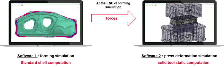
Currently acceptable workflow for analyzing tool distortion.
When Forming and Structure Started Talking
The breakthrough came with a coupled simulation approach inside Keysight Stamping.
Instead of running forming first, and structure afterward, both simulations start at the same time. The blank deforms in one solver, while the tools and press structure deform in another. Throughout the stroke, typically up to 150 times, forces and displacements are exchanged.
The blank influences the structure.
The structure influences the blank.
In real time.
Suddenly, the model reflects what truly happens in the press.

Proposed workflow for including tool and press distortion during forming simulation.
The Hood Example
For practical and logistical reasons, tools for different parts are often tried out separately, sometimes even in different presses or workshops, where forming issues are addressed independently for each tool. Only later in the process, often shortly before the start of production, are these tools combined in the same press as planned for the final production setup. At that stage, the interaction between the tools can change the overall force distribution on the press, potentially causing structural effects such as ram or cushion tilting and resulting in unexpected imbalances. This may lead to additional and unplanned try-out loops. Being able to capture these interactions early in simulation helps anticipate such late-stage issues and significantly reduces the risk of costly adjustments just before production launch.
To understand the impact, consider a realistic scenario: a hood inner and hood outer stamped together in one press stroke. This configuration naturally generates imbalance because the force distribution is not perfectly symmetric.
Three simulations were performed.
In the first, only the blank was deformable. Tools and press were rigid.
In the second, the blank and tools were deformable, but the press structure remained rigid.
In the third, blank, tools, and full press structure were all elastic and fully coupled.
When only the tools were allowed to deform, the punch showed about 0.1 mm of displacement. The blank holder and die deformations were minimal. It seemed manageable.
But when the press structure was included, everything changed.
The RAM exhibited noticeable rotation. The lower structure of the press deflected. Displacements increased to roughly 0.27–0.33 mm. The imbalance propagated through the entire system. The inner hood showed significantly higher deformation. The outer hood’s displacement pattern shifted toward the center of the press.
The deformation was no longer local.
It was systemic.
What Changed on the Blank?
Structural displacement is interesting. But what matters most is what happens to the part.
In the rigid simulation, contact between tools and blank appeared uniform. The forming limit diagram was predominantly green. The part seemed approved.
When tools were elastic, subtle contact changes emerged. Areas of insufficient stretching began to appear.
When the full press was elastic, the differences became undeniable. Contact zones shifted significantly. Radii were not fully formed. Insufficient stretching increased. The inner hood, in particular, showed strong sensitivity in springback behavior.
A part that looked perfectly acceptable in a rigid simulation was no longer acceptable when structural compliance was considered.
The simulation had not been wrong.
It had been incomplete.

Forming limit diagram (FLD) results for the initial rigid tools simulation (left) and the simulation with deformable tools and press (right).
Beyond Accuracy: New Possibilities
Once engineers saw the predictive improvement, new applications naturally emerged.
If tool and press deformation can be calculated, it can be compensated digitally. Virtual die spotting becomes possible and realistic.
If different press models can be introduced, engineers can simulate the difference between tryout press and production press before physically moving the tool. This “digital tryout” reduces ramp-up uncertainty.
Force center evolution can be tracked during the stroke. Since maximum press capacity depends on centered loading, balancing strategies can be tested virtually.
Even cam closure in flanging operations can be evaluated more realistically, preventing surprises caused by structural deflection.
The technology did not just solve one problem.
It opened new doors.
Computation Time: A Practical Question
One of the immediate concerns with coupled simulations is calculation cost.
Encouragingly, the example hood case ran overnight. Longer than a standard rigid simulation, yes, but well within acceptable industrial timeframes.
The gain in predictive accuracy far outweighs the additional computational effort.
Especially when compared to weeks of tryout iterations.
A Turning Point in Simulation Philosophy
There was a time when ignoring springback was acceptable. That time passed.
Today, ignoring structural compliance is entering the same category.
As forming forces increase and press utilization becomes more aggressive, assuming rigid tools and press structures becomes less defensible.
The introduction of elastic tool and press deformation is not about adding complexity for its own sake. It is about aligning simulation with physical reality.
It reduces the risk of unpleasant surprises.
It shortens the path from digital validation to production stability.
It transforms simulation from an approximation into a closer mirror of what truly happens when thousands of kilonewtons flow through steel structures.
And perhaps most importantly, it shifts the mindset of stamping engineering.
Because when the press started to bend, and the simulation finally acknowledged it, digital manufacturing took one more decisive step toward reality.
If you are curious and want to learn more about stamping simulations including tool and press deformations, register for one of our upcoming free webinars:
AMO- Webinar: Incorporating tool and press deformations in stamping simulations to enhance part quality …
EMO- Webinar: Incorporating tool and press deformations in stamping simulations to enhance part quality …
APAC- Webinar: Incorporating tool and press deformations in stamping simulations to enhance part quality …
Or visit the Stamping Simulation webpage
Related Posts