
Stray Light Analysis of AR Waveguides Using k-Space
Waveguide combiners used in augmented reality (AR) near eye displays exhibit optical behavior that differs substantially from conventional refractive systems. As field of view requirements increase and mechanical constraints tighten, the number of possible propagation paths inside the substrate grows, and many of these paths lead to stray light artifacts that are difficult to diagnose in real space or challenging to suppress during optimization. k Space analysis provides a compact and architecture agnostic method for understanding these behaviors, and a possibility to reduce/eliminate the stray light before the optimization. By representing propagation in terms of transverse wave vectors, (kx, ky), it becomes possible to identify allowable propagation regions, clipping boundaries, and stray light paths before running full non sequential simulations or optimization.
This article outlines how k space can be applied to surface relief grating (SRG) and geometrical waveguides (GWG), and how it supports a structured workflow for diagnosing and mitigating stray light.

Figure 1: k diagram of SRG WG
Waveguide Behavior in k‑Space
A k‑diagram consists of two concentric circles: the inner circle corresponding to the ambient medium and the outer circle corresponding to the waveguide substrate. Any point between these circles represents a guided mode. This representation immediately shows which propagation directions satisfy total internal reflection and which do not. It also reveals how the field of view occupies the available region and how it interacts with design constraints such as maximum incident angle or pupil‑replication boundaries.
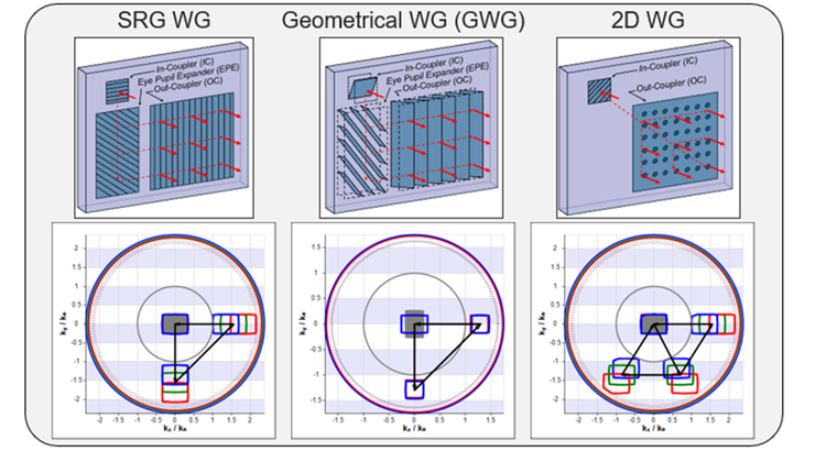
Figure 2: Light is deflected at in-coupler (IC), pupil expander (EPE), and out-coupler (OC).
In practice, k‑space provides immediate visibility into several key aspects of waveguide behavior:
- Field‑of‑view placement: Whether the FOV fits within the total‑internal‑reflection region.
- Propagation limits: Where clipping occurs due to angular or mechanical constraints.
- Grating or mirror interactions: How each element shifts or rotates the FOV.
- Dispersion behavior: How RGB wavelengths separate or overlap.
- Order management: Where higher‑order diffraction or reflection paths land.
These features make k‑space a useful first‑order tool for both SRG and GWG architectures. In SRG waveguides, grating vectors translate the FOV; in GWGs, mirror reflections rotate it. Two‑dimensional waveguides introduce additional complexity by splitting the FOV into two independent k‑space copies. Across all architectures, the k‑diagram provides a unified way to visualize propagation behavior.
Stray‑Light Mechanisms Revealed in k‑Space
Stray light in waveguides is structural rather than incidental. Once propagation paths are expressed in k‑space, the origins of these artifacts become clear.
Undesired Diffraction Orders (SRG)
Higher‑order diffraction appears as additional translated copies of the FOV. These orders often:
- Fall inside the guided region but outside the intended FOV envelope.
- Exhibit strong wavelength dependence, with blue ghosts typically appearing first.
- Interact with mechanical boundaries, producing clipped or truncated artifacts.
Back‑Surface and Double Reflections (GWG)
Mirror‑based architectures introduce their own characteristic stray‑light paths:
- Back‑surface reflections create translated copies of the FOV displaced from the main path.
- Double reflections (IC→WG surface→IC, OC→WG surface→OC) generate additional translated paths.
- These paths may overlap the desired output, making them difficult to detect in real‑space images.
Ambient‑Light Interactions
Rainbow and viewer‑appearance artifacts map cleanly into k‑space:
- A single ambient light wavelength produces a predictable region between an arc and the inner circle in the user’s FOV.
- The corresponding viewer‑appearance arc is the symmetric counterpart.
- Even broadband illumination can be modeled using a small set of discrete wavelengths.
Dispersion from Non‑Closed Grating Triangles
If the IC, EPE, and OC vectors do not form a closed loop:
- Red, green, and blue exit at different k‑positions.
- The FOV shears or shifts laterally.
- Visible color fringing appears across the image.
k‑Space makes these issues immediately visible, often long before they appear in simulation or hardware.

Figure 3: Stray light paths have representations in the k-space
Workflow for k‑Space–Driven Waveguide Design
A practical workflow begins by defining the field of view, eye box, substrate index, and grating vectors or mirror angles. Once these parameters are set, the k‑diagram shows whether the field of view fits within the total‑internal‑reflection boundaries and whether any part of it clips. It also shows where stray‑light paths land relative to the eye box or external viewing directions.
Typical early‑stage checks include:
- Does the FOV remain fully guided across the wavelength band?
- Do any higher‑order grating interactions fall inside the eye box?
- Do mirror rotations produce overlapping copies of the FOV?
- Is the grating triangle closed (for SRG architectures)?
- Do ambient‑light arcs intersect the eye box?
Adjustments to grating vectors or mirror angles can be made directly in k‑space, and the effects are immediately visible. After the k‑space layout is correct, full optical modeling is used to quantify stray‑light levels, evaluate undesired diffraction order power, and perform image‑source analysis. Because the k‑space analysis has already eliminated most problematic paths, the simulation tends to converge more quickly and with fewer unexpected artifacts.
Representative Examples
Several recent examples illustrate how this workflow operates in practice.
- SRG ghosting:
A 40°×30° SRG design exhibited a blue‑dominant ghost at the left edge of the eye box. The k‑diagram showed that second‑order OC diffraction was landing inside the eye box. A small adjustment to the IC (kx) component moved the undesired order outside the visible region. - GWG back‑surface reflection:
A GWG design with a 97° input rotation produced a rotated ghost overlapping the main FOV. The k‑diagram made the overlap clear, and increasing the rotation to 98° resolved the issue. - Rainbow and viewer‑appearance behavior:
Ambient illumination produced a rainbow arc in the user’s FOV and a symmetric viewer‑appearance arc visible externally. The clipping of these arcs matched the OC and eye‑box geometry exactly as predicted. - Dispersion from grating mismatch:
A west‑globe test image showed blue tint on one side and red on the other. The k‑diagram revealed that the IC, EPE, and OC vectors did not form a closed triangle. Correcting the vectors restored uniform color performance.
These examples demonstrate how k‑space provides early visibility into stray‑light behavior and supports targeted corrections.
Conclusion
k‑Space analysis provides a concise and effective method for understanding waveguide propagation, identifying stray‑light paths, and guiding design decisions. It reduces the complexity of waveguide behavior by revealing the underlying structure of propagation paths and allows stray‑light mechanisms to be identified early, before they become costly to correct. When combined with full optical simulation, it forms a complete workflow that supports efficient iteration and more predictable hardware outcomes. For AR waveguides, where small geometric changes can produce large optical consequences, k‑space has become an essential tool for engineering analysis.
This article was written in collaboration with Dr. William Cassarly.
The Waveguide Designer is available in the latest release of LightTools. Ask for an evaluation.
SPIE Presentation and Paper: Stray light analysis of AR waveguides in k-space