
Slim Design: How to Create a Signal Lamp with Thousands of Optical Elements
Creating a signal lamp with a sleek, modern design involves intricate optics and the use of advanced software tools. In this blog post, we'll explore how to achieve a thin appearance for automotive lighting using LucidShape CAA V5 Based software. We'll look into the use of the MacroFocaldesigndesign features for arranging thousands of reflectors and lenses and provide tips for efficient design and simulation.
Introduction to LucidShape CAA V5 Based Software
LucidShape CAA V5 Based is a powerful tool for automotive lighting design, allowing engineers to create complex lighting systems with precision. In our example, we use a sports car model as a reference to demonstrate the process of designing a signal lamp with thousands of optical elements.
The primary objective of this design is to create a uniform lit appearance that meets light distribution regulations. The design process involves using a Class A Surface which will be populated with a pillow lens optic to increase the uniformity of the lit appearance under various viewing angles.
Initial setup and design feasibility
The design begins with the initial CAD data, which includes the taillamp housing and the outer lens with the Class A Surface section. Before diving into the complete design, it's crucial to review the feasibility of designing with a single system.

Figure 1. For the single system, we use a reflectors-lens couple which is split into multiple facets to achieve a uniform lit appearance on the outer surface
Using the LucidShape CAA V5 Based 2023.06 version, we configure the single system with a reflector defined by multiple facets using the MacroFocal Reflector design feature, a light source pointing towards the reflector, an inner lens with multiple facets projected onto the Class A Surface using the MacroFocal Lens design feature, and a surface texture applied from the SmartStart Library Module.
Arraying the optical elements
To achieve an array of optical elements, we use the horizontal center curve of the Class A Surface as the reference for the reflector and lens array. Defining reflectors in sections is more efficient than using individual MacroFocal design features for each reflector. This approach minimizes unnecessary computation time and allows for specific sections to be activated as needed.
In our example, equally spaced planes are placed when viewing the system from the front, creating intersections with the reference curve. Parameters are defined using formulas to automatically calculate the starting point for the next section, making it easy to adjust the number of instances during the design process.

Figure 2. Multiple reflector array utilizing the User Pattern
Arranging light sources and lenses
The next step involves arranging multiple light sources. We suggest two methods: using the User Pattern of CATIA or the Axis Pattern of LucidShape CAA V5 Based. The User Pattern method is faster and creates fewer objects in the design system, while the Axis Pattern method is necessary for analyzing the on/off state of individual light sources.
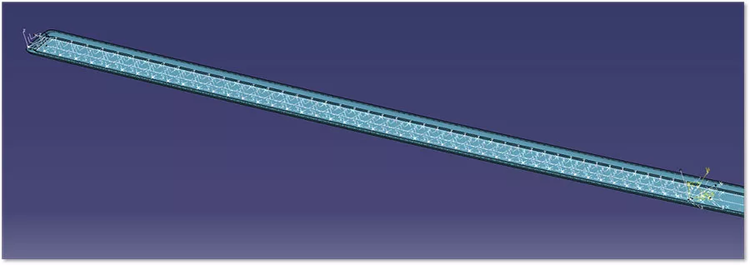
Figure 3. Defining light sources with Axis Patterns: Individual light source definitions are required to see lit appearance with various scenarios applied.
For arranging lenses, we split the lens into multiple regions and use the MacroFocal Lens design feature. This method reduces computation time and handles cases where the projecting surface does not cover the entire rectangular area. We also utilize the Simple Spread option to solve optical surface calculation problems at the fringes of the system.
Simulation and analysis
Once the design is complete, we simulate the lighting system using the Ray Tracing Simulation feature in LucidShape CAA V5 Based. The Design Table feature in CATIA allows us to control parameters and modify geometry efficiently, including the simulation of individual LEDs. Simulation results can be analyzed using the Advanced Analysis utility, where we can evaluate regulations, group LID files, and perform adjustments such as scaling, aiming, and shifting.

Figure 4. By controlling the Scale parameter in LucidShape CAA V5 Based, you can see the result of dimming and turning each light source on and off
Conclusion
Designing a signal lamp with thousands of optical elements requires careful planning and the use of advanced software tools like LucidShape CAA V5 Based. By leveraging features such as MacroFocal Reflector and Lens design, User Patterns, and Advanced Analysis, engineers can create efficient and precise lighting systems. The ability to simulate and analyze the design ensures that the final product meets regulatory standards and achieves the desired uniform appearance.