
LightTools 2026: Advancing Optical System Simulation With GPU Acceleration, VisionSym Integration, and Stray Light, AR Waveguide, Meta-Optic Lens, and CAD Import Workflow Enhancements
Modern optical system design increasingly demands higher model fidelity, larger ray counts, and tighter design iteration cycles. Engineers working in illumination, stray light, AR/VR, meta-optic lens systems, and non-imaging optics often face practical limitations driven by simulation time, memory usage, and workflow complexity—especially when models incorporate detailed CAD geometry, scattering effects, and specialized optical properties exhibiting wave-optics phenomenon such as spatially-varying surface relief gratings.
LightTools 2026 introduces significant new features and enhancements aimed at eliminating these limitations.
GPU Acceleration
The challenge: Long runtimes for high-ray-count models
Ray tracing is a very important tool for modeling many optical systems. Many systems require tracing lots of rays to reduce noise to the desired fidelity — hundreds of millions or more — to achieve acceptable noise levels. On CPU-only workflows, this quickly becomes a limiting factor during design iteration.
What’s new in LightTools 2026
LightTools 2026 introduces GPU acceleration for many forward ray trace features, with a multi-release plan to expand coverage further.
Supported features include:
- Point sources and most surface sources, including fully immersed sources
- Many receiver types and meshes
- Gegenenbauer and Henyey-Greenstein volume scattering
- Measured BSDF and Microfacet scatter models
- Optical contact and cementing
- Use of the Accelerated Ray Trace slider to control tessellation level
- Observed speedups are model- and hardware-dependent but commonly fall in the 10× to 50× range, with some models showing even larger improvements.
Use case examples:
- Immersed source simulations with large ray counts
- Compact aspheric lens systems
- Geometric near-eye display models

Figure 1. Immersed source example using an RTX5000 Ada GPU card, where the GPU trace yields a 2-second render time that is 62.5x faster than a standard forward trace.
Why it matters
Because of the substantial speedup it can deliver, GPU acceleration allows engineers to run higher-fidelity simulations earlier in the design process, reducing reliance on approximations during preliminary exploration. This directly improves confidence in performance predictions without extending iteration timelines.
VisionSym Integration for GPU-Accelerated Backward Ray Tracing
The challenge: Visualizing complex scenes accurately and interactively
Backward ray tracing is widely used for luminance-based analysis and visual assessment, but when it is CPU-based, backward ray tracing can struggle with models that have detailed scattering, complex geometry, or the need for interactive inspection.
VisionSym in LightTools 2026
LightTools 2026 integrates with VisionSym, the Keysight GPU-accelerated backward ray tracing engine designed for progressive, interactive visualization.
Key capabilities include:
- 10×–30× or more speed improvements compared to standard LightTools backward ray trace
- Progressive image refinement during interactive camera movement: each time you stop rotating the view, the rays continue tracing and updating the image
- Automatic aiming for scatter surfaces exposed directly to sources to make traces even faster
- Specialized algorithms for reduced pixel noise
- LightTools can also use the VisionSym engine for backward ray trace luminance camera traces using standard LightTools plots, meshes, and Parameter Analyzer
- Allows you to use Environment Sources — a feature that VisionSym inherits from LucidShape products
VisionSym uses the LightTools Luminance Camera Receiver for parameter storage and view orientation and supports synchronized parameter exchange between LightTools and VisionSym.

Figure 2. Synchronization between LightTools and VisionSym. This model uses an environment source to make the background and Henyey-Greenstein volume scattering.
Practical benefits
For engineers evaluating visual artifacts, glare, stray light patterns, or human-perceived quality, VisionSym enables a more interactive workflow. Instead of waiting for an image to trace, engineers can rapidly inspect problem areas and adjust geometry, materials, or aiming strategies in near real-time.
Stray Light Workflow Enhancements
The challenge: Managing large numbers of ray paths and memory usage
Stray light analysis frequently involves tracing a very large number of rays through primary optical paths while only a small subset contributes meaningfully to unwanted artifacts. This can result in excessive memory demands and slow post-processing.
Improvements in LightTools 2026
LightTools 2026 introduces several important enhancements that improve stray light analysis efficiency:
- Options for importing and exporting ray path files (same format as sequence files)
- Ability to limit the number of rays per path
- Improved Compute Filtered Mesh Data option that applies to only enabled ray paths
- Updates to the Ray Path Analyzer utility
- Expanded Surface Set selection and visualization
Surface Sets allow multiple physical surfaces to be treated as a single ray path contributor, dramatically reducing the number of generated paths — particularly when analyzing complex CAD models.

Figure 3. Surface Set Selection and Visualization
Why it matters
These enhancements significantly reduce memory usage and computation time, making it practical to explore stray light mitigation strategies without simplifying the underlying geometry.
AR Waveguide Designer for Geometric and Grating-Based Systems
The challenge: Coordinating k-space, uniformity, stray light, and color performance
AR waveguide systems combine optical coupling, pupil expansion, diffraction, and stray light control into a tightly interdependent design space. Managing these relationships manually — especially for spatially varying grating designs — can be error-prone and time-consuming.
LightTools 2026 approach
The AR Waveguide Designer provides a structured environment for:
- Setting up designs using k-space diagrams
- Automatically creating Input Couplers (IC), Eye Pupil Expanders (EPE), and Output Couplers (OC)
- Supporting geometric mirror-based, surface relief grating (SRG), and Volume Bragg Gratings (VBG) approaches
- Analyzing angular luminance, eyebox illuminance, image quality, and stray light paths
Spatial variation in gratings can be controlled using LightTools grid expressions, with seamless integration of RSoft UDOP data for rigorous Electromagnetic (EM) based grating behavior.
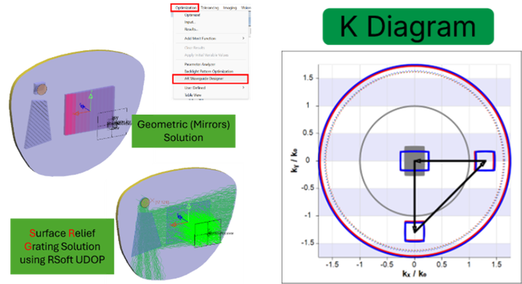
Figure 4. Examples of geometric and surface relief grating waveguide systems designed using k-space.
Differentiation value
The tight integration between the grid expressions and RSoft-based optical properties via extended BSDF data enables system-level ray-based simulation while preserving physically accurate grating behavior — an area where many competing workflows require disconnected tools and manual data handling.
Meta‑Optic Lens Modeling
Meta‑optic lenses (also known as metalenses) enable compact optical functionality through sub‑wavelength structures that control phase, wavelength, and polarization. While these components are typically designed using rigorous electromagnetic methods, system‑level performance still depends on how the meta‑optic interacts with sources, surrounding optics, mechanical structures, and scattering surfaces.
LightTools 2026 enables system‑level simulation of meta‑optic lenses by representing EM‑derived meta‑optic behavior as physically accurate optical surface properties. Using extended BSDF and surface models, LightTools captures wavelength‑ and polarization‑dependent behavior while allowing meta‑optic lenses to be analyzed within full ray‑based illumination, imaging, and stray light models.
This approach allows engineers to evaluate throughput, efficiency, stray light generation, and sensitivity to source conditions without removing the meta‑optic from its system context. Meta‑optic lenses can be modeled alongside conventional optics, CAD geometry, and scattering surfaces using a single, unified workflow.

Figure 5. Meta optic lens controls
LightTools meta‑optic modeling complements RSoft electromagnetic solvers, enabling engineers to carry rigorously designed meta‑optic behavior into system‑level simulations without manual approximation. Together, these tools support faster iteration and more reliable performance prediction as meta‑optics transition from isolated designs to integrated optical systems.
CAD Model Import with Preserved Assembly Structure
The challenge: Maintaining design intent when importing complex CAD assemblies
Imported CAD geometry often loses naming, hierarchy, and colors that you added in the CAD package itself, making it harder to assign optical properties, group surfaces, or perform targeted analyses.
Enhancements in LightTools 2026
The Import > CAD Model workflow now supports additional CAD formats (NX, Creo, and Rhino), and it imports more information from your CAD model:
- Maintains assembly and sub-assembly hierarchy, with separate primitives for each part
- Preserves sub-assembly and part names
- Preserves object color
- Maintains receivers for individual surfaces
- Maintains optical properties at the part level or by surface
New display options allow object color to be used consistently across surface rendering, wireframes, and section planes.

Figure 6. LightTools can now preserve the assembly structure, names, and colors when you import a CAD assembly.
Why it matters
Preserving CAD structure significantly reduces setup time for optical simulation, particularly in systems where mechanical and optical design are tightly coupled.
Conclusion
LightTools 2026 focuses on reducing common barriers in system-level optical simulation as models grow in complexity and fidelity. GPU acceleration and VisionSym integration improve iteration speed and interactive visualization, while workflow enhancements streamline stray light, AR waveguide, and CAD-based modeling. Expanded support for meta-optic lens modeling further enables engineers to integrate EM-derived meta-optic behavior into full system simulations, preserving physical accuracy while maintaining efficient ray-based analysis. Together, these capabilities position LightTools 2026 as a scalable, integrated platform for evaluating advanced optical systems from concept through system-level validation.
Learn more:
- On the web: LightTools
- Download: What’s New in LightTools 2026
Request trial:
Related Posts