
Build Ultra-Realistic PNT Test Scenarios with 3D Terrain Modeling in PNT X
Developers of positioning, navigation, and timing (PNT) equipment usually have to sacrifice realism when testing with simulators in the lab. No simulator can ever replicate the true richness of the real-world environment, making field testing an important part of the development cycle.
But it’s now possible to get closer to real-world conditions in the lab with Keysight PNT X, the world’s most advanced PNT simulation platform.
One way PNT X takes a huge step forward in realism is in modeling signal propagation patterns. Its 3D terrain modeling feature allows developers to create realistic physical environments into which transmitters and receivers can be placed. Developers can model and evaluate the impact of signal multipath, obscuration, and diffraction on signal transmission and reception in detail.
How 3D terrain modeling works in PNT X
In the past, developers had two choices: use a simulator’s inbuilt statistical models to approximate the impact of signal multipath and obscuration, or invest in supplementary ray-tracing and 3D modeling software to recreate authentic signal paths in real or geo-realistic locations.
With PNT X, developers get all the benefits of the second option as standard. Its inbuilt 3D terrain modeling feature uses 3D maps to generate accurate obscuration, diffraction, and multipath signatures relative to a receiver’s antenna. Users can import their own maps or use pre-loaded maps of cities and landscapes from around the world.
Multiple antennas and receivers can be placed into the environment, allowing complex scenarios to be simulated with a high degree of realism. The whole environment can also be visualized for real-time insight into the effects of obstacles on signal reception during the scenario. Developers can load maps and set up the environment quickly and easily.
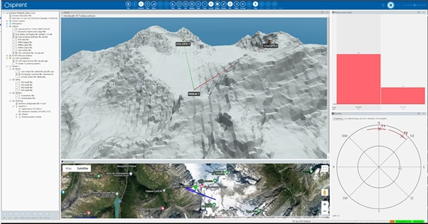
3D visualization of a scenario: an aerial vehicle moves through a mountainous location, passing two independent L1 jamming beacons. One of the beacons is temporarily obscured by the terrain.
Understand the impact of obscuration, diffraction, and multipath
The 3D terrain modeling feature provides unprecedented insight into three key effects of the physical environment on radio frequency (RF) signals: obscuration, diffraction, and multipath.
- Obscuration*:* Obscuration occurs when a signal is entirely blocked by an environmental feature, such as a building, hillside or rock outcrop. Realistic obscuration modeling shows how many satellites will be in view at any given time along the modeled trajectory in the chosen physical location.
- Diffraction*:* Diffraction occurs when a signal bends around an obstacle in the environment. Diffraction can attenuate the signal’s power level and elongate its path, creating a delay that can result in inaccurate pseudorange measurements. Developers can model diffraction to understand the impact on signal reception and positioning accuracy in a given location.
- Multipath*:* Multipath occurs when a signal reflects off the surface of a structure in the environment, such as a building or rock face. This typically causes signal delays that can affect positioning accuracy. Multipath is particularly problematic in built-up areas where there may be more reflected signals than line-of-sight (LOS) signals.
The ability to model all of these effects in real-world locations means teams can now perform some testing in the lab that was previously only possible in the field — often on a dedicated test range. As a result, teams can accelerate product development cycles and reduce associatedcosts.
Go “beyond GNSS” with support for alternative PNT and external user-defined signals
The 3D terrain modeling capability is even more powerful when combined with other groundbreaking features of PNT X. Designed for a world “beyond GNSS,” it allows not just GNSS signals but many other signals and waveforms to be modeled in a 3D environment. For example:
- LEO PNT: PNT services delivered from Low Earth Orbit (LEO) constellations are starting to provide a valuable complement to global navigation satellite system (GNSS) signals. However, as LEO satellites are more numerous and faster-moving than GNSS satellites, it can be challenging to understand their obscuration, diffraction, and multipath signatures. PNT X makes it easy, either by injecting custom LEO PNT signals as In-Phase / Quadrature (I/Q) files and adding them to the 3D environment, or by using the certified in-built SimXona tool to model the signals of the Xona PULSAR constellation.
- Custom I/Q files: The patented SimIQ spatial awareness capability applies realistic effects — including power level offsets, signal delays and Doppler shift — to signals injected into the simulator as pre-recorded I/Q files, allowing those signals to be simulated with unprecedented realism. The tool automatically adds the effects to the transmitted signals based on the positions of transmitter and receiver relative to the device under test. By placing I/Q-defined transmitters (static or dynamic) into the 3D environment, developers of custom signals and waveforms can gain realistic insight into their obscuration, diffraction and multipath signatures.
- Interference: Testing against jamming and spoofing has been a critical element of defense development for many years, and that importance is now transferring to civilian applications. For this testing to have the greatest value, the scenarios need to be realistic, and that involves imparting the same environmental conditions on the interferers and the devices under test as they would experience in the real world. In addition, some recent testing has yielded interesting results regarding the impact of diffraction on interfering signals — look out for more on that in the near future!
PNT X: Bringing exceptional realism to the PNT test lab
3D terrain modeling is just one of the many groundbreaking features offered in PNT X, designed to test the limits of precision, robustness, and resilience for mission-critical systems.
As the world’s most advanced PNT simulation platform, it brings unprecedented realism to the PNT test lab, enabling teams to test more, earlier, and build confidence in the results. If you’d like to learn more about Keysight PNT X, explore the Keysight PNT X product page.