Confirm Your Country or Area
Please Confirm
Confirm your country to access relevant pricing, special offers, events, and contact information.
What are you looking for?
Adjusting NPLC and Aperture to make high speed measurements
Note: This applies to the 34401A, 34970A, and 34980A products.
NPLC sets the integration time in Number of Power Line Cycles. Integration time is the period of time that the instrument's analog-to-digital (A/D) converter measures the input signal. NPLC is used for DC voltage and current, two and four wire resistance, and temperature measurements.
NPLC commands
[SENSe:]VOLTage[:DC]:NPLC {


  |MIN|MAX|DEF} [, (@


   )]
        CURRent
[SENSe:]FRESistance:NPLC {


    |MIN|MAX|DEF} [, (@


     )]
        RESistance
        TEMPerature
Note: Channel lists are not used for the 34401A.
NPLC values: {0.02|0.2|1|2|10|20|100|200}.
When determining the value of a dc signal, there oftentimes exists some power line-induced ac noise. Integrating the dc signal over one or more power line cycles helps to reject this noise. If the noise is at the line frequency (60Hz in the U.S., 50Hz in most other countries), it can be removed over one cycle. Sometimes however, the noise is not uniform, and the signal should be integrated over multiple cycles. The greater the number of power line cycles, the more accurate the signal value will be, i.e. greater noise rejection and better resolution. If your application simply calls for a true/false or high/low voltage reading, minor noise will not be a major factor in achieving the desired value, and you can use a very small NPLC to maximize throughput.
The NPLC parameter is automatically set to 1 PLC (default) after cycling power or the *RST command. This is a good general value to use. NPLC values ≥ 1 provide very precise readings but with a tradeoff of speed. Only NPLC values ≥ 1 PLC will provide noise rejection. The faster you can take readings the more the instrument acts like a digitizer. From Figure 1, you can see that taking 20 samples with .02 PLC gives a faithful representation of the waveform seen by the unit (0.5V ac 60Hz hum with 5V offset). Conversely, if 1PLC is used, the correct dc value of 5V is revealed by canceling out the effect of the ac noise. An NPLC ≥ 1 provides a closer approximation of the true dc value.
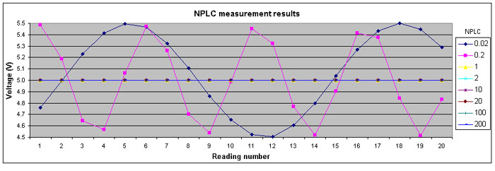
Figure 1. A test program for the 34980A using the 34951 DAC card created a 60 Hz sine waveform to display a 1V p-p 60 Hz ac voltage with 5V dc offset. The results show the voltage measured for each NPLC value across 20 readings with autozero disabled.
What is the relationship between NPLC and speed? You can conduct faster measurements by specifying shorter integration times. Other settings will affect the speed as well. As discussed in Article 1 of this series, disabling autozero can approximately double the measurement speed. Figure 2 shows that the timesaving of autozero ON vs. OFF is fractions of a second for smaller NPLC values. For large NPLC values (≥ 10), the timesaving greatly increases, up to large portions of a minute or more. Note however, that when specifying large NPLC values, it is recommended to enable autozero to maximize accuracy.
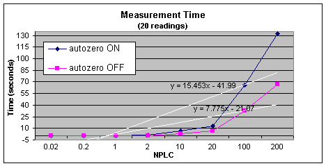
Figure 2. This graph was derived in a test program for the 34980A using autozero ON vs. OFF for each NPLC value, across 20 readings on the DMM. DC VOLT, range 10, and function calls INIT and FETCH? were used to measure a 1V p-p 60 Hz ac voltage with 5V dc offset.
Some non-Keysight DMMs require that you specify the line frequency in use. When developing a program in one country and using it in a country with a different line frequency, it is easy to forget to change this command. Modern Keysight DMMs are able to automatically detect the line frequency and adjust the integration time appropriately. Why is this important? Let’s say you write a program specifying 60 Hz, and then apply this program to a non-Keysight DMM in a country with 50 Hz line frequency. If the program is not adjusted, there will be 50 Hz ac noise that will not be cancelled out, leading to inaccurate readings.
Integration time can also be specified in seconds, rather than in cycles. The APERTURE setting allows for more precise control over the length of the cycle. Aperture is used for DC voltage and current, two and four wire resistance, temperature, period, and frequency measurements
Aperture commands
	[SENSe:]VOLTage[:DC]:APERture {


  |MIN|MAX|DEF} [, (@


   )]
        CURRent
[SENSe:]FREQuency:APERture {


    |MIN|MAX|DEF} [, (@


     )]
        FRESistance
        RESistance
        PERiod
        TEMPerature
Specifying integration time using NPLCs is more commonly practiced because it executes faster and is simpler to configure than using Aperture, which requires careful calculation. Aperture commands allow a 4us resolution, which can help you specify a specific integration time between 300us and 1s. However, unless there is an exact integration time you wish to achieve, the NPLC setting can accomplish your task with greater ease. When using Aperture mode, NPLC mode is disabled and vice versa.
The integration time and resolution are directly linked; setting one will automatically set the other. The following table shows the relationship between integration time, measurement resolution, number of digits, and number of bits. If you change the range after setting the resolution, the integration time will not change but the resolution will be changed to match the integration time of the new range. Note that when you specify resolutions [e.g., CONF:VOLT:DC range, resolution, (ch_list)] corresponding to an NPLC <1, autozero will automatically be disabled.
| Integration Time | Resolution | Digits | Bits |
|---|---|---|---|
| 0.02 PLC | < 0.0001 x Range | 4 1/2 Digits | 15 |
| 0.2 PLC | < 0.00001 x Range | 5 1/2 Digits | 18 |
| 1 PLC | < 0.000003 x Range | 5 1/2 Digits | 20 |
| 2 PLC | < 0.0000022 x Range | 6 1/2 Digits | 21 |
| 10 PLC | > 0.000001 x Range | 6 1/2 Digits | 24 |
| 20 PLC | < 0.0000008 x Range | 6 1/2 Digits | 25 |
| 100 PLC | < 0.0000003 x Range | 6 1/2 Digits | 26 |
| 200 PLC | < 0.00000022 x Range | 6 1/2 Digits | 26 |
Table 1. Correlation of integration time, measurement resolution, number of digits, and number of bits.