Can I use a vector signal analyzer (VSA) to measure group delay of a digitally-modulated signal?
Operational "How to" Guides
Summary
How to use a vector signal analyzer (VSA) to measure group delay of a digitally-modulated signal?Description
The 89600S and 89400 families of vector signal analyzers can be used to measure the group delay of a digitally-modulated signal. The approach is to use the general-purpose adaptive equalizer that is built in to the demodulation capability of the VSA. This function is included in options AYA and AYH on the 89400´s and AYA on the 89600´s.
Adaptive EQ removes linear distortion like group delay, frequency response and multipath from the measured signal so EQ may be used as either a measurement or troubleshooting tool. The only requirement is that the modulation format be one that is known to the demodulator. For a complete list of formats supported by these options, please refer to the product data sheets on our website.
The method is to turn on the VSA digital demodulator, set up the demodulation parameters like format, symbol rate and filtering so that a good constellation is obtained, turn on the adaptive equalizer, adjust EQ length and convergence as needed and wait until it has finished working, i.e. EVM in the error summary is no longer improving, view the frequency response measurement data, and format the data to group delay. Then apply a marker and offset marker to obtain the peak-to-peak value in the channel.
For example, here are the keystrokes for an 89441A measuring an off-air DTV (8VSB) signal:
The A trace should now show the group delay response of the channel. Place a marker and an offset marker on the maximum positive and negative excursions within the channel for a peak-to-peak group delay that should look something like this:
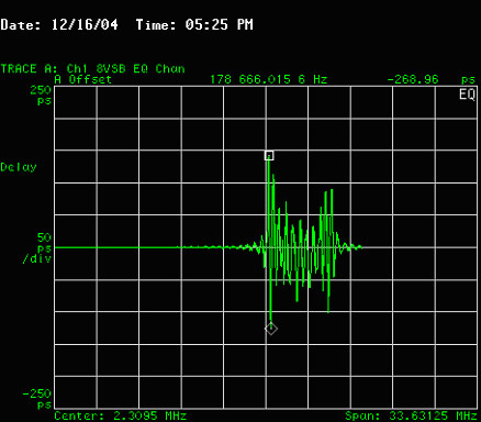
The channel frequency response displays the inverse coefficients of the equalizer, which is equivalent to the frequency response of the channel. This data can be formatted to log magnitude, group delay, phase or other formats. The equalizer length and convergence should be adjusted for best results. The length defines the total length of time in terms of symbols over which the coefficients are calculated, and convergence determines the rate at which they are calculated where a larger convergence value is faster. The length and number of points per symbol (points/symbol under the Time hardkey) together determine the number of taps on the filter. Points/symbol (4 in the example above) also affects the displayed span. For more information on the equalizer, its length and convergence functions refer to the built-in Help feature of the 89400 or 89600A VSA.
You may notice that the channel data is offset to the right in the display by 3 MHz or half the channel bandwidth, which in this case is 6 MHz. The offset is due to the vestigial sideband nature of the 8VSB signal where the Q waveform has the effect of nulling one sideband or the other, depending on whether the pilot (carrier frequency) is high-side or low-side. The VSA digital signal processing (DSP) does not "know" about the suppressed sideband, and simply treats the pilot as the center frequency of a 12 MHz signal.
This is an example of using this general-purpose equalizer to capture the actual response of the unequalized, or "raw" channel. In a real-world receiver, an application-specific equalizer would be used. If this specialized equalizer were placed in line with the signal coming into the VSA, then the VSA´s general-purpose equalizer would be measuring an equalized channel, which is disallowed by some standards. In our methodology, the equalizer is simply used as a tool to capture the desired data on a channel with no equalization.
The adaptive equalizer in the 89400 and 89600 families of vector signal analyzers is a powerful tool for measurement and analysis of vector-modulated signals.